Troubleshooting series vl units – Bell & Gossett DN0135D Domestic Pump Vacuum Heating Units Series VL User Manual
Page 8
(3)
Place motor vertically with pump end up. Do not attempt
assembly of seal and impeller with shaft horizontal.
(4) The “carbon” of rotating part of seal should not be loose.
If it is, hold in place with grease, Using clean, lint free
cloth, wipe mating surfaces perfectly clean. Soap shaft
and push seal onto shaft so that carbon will contact
ceramic seal. If spacer is required, use grease to cause
spacer to adhere to bottom of seal after seal has been
put on shaft. Be sure spacer is on larger diameter of
shaft so that will not catch between shoulder and
impeller.
13. Replace impeller on shaft. Replace stainless steel washer
and secure impeller with capscrew or cap nut.
14. Place new gasket on pump volute and reassemble motor
and pump subassembly on pump volute.
15. Reconnect pump bleed line and motor wiring.
16. Close drain and slowly open inlet valves. See warning.
17. Jog to check motor rotation. See caution.
18. Observe operation thru several cycles.
8
CAUTION:
DO NOT REVERSE
Reverse operation can cause extensive damage to
pumps. Jog the motor to test for direction of rotation. Failure
to follow these instructions could result in serious injury or
death.
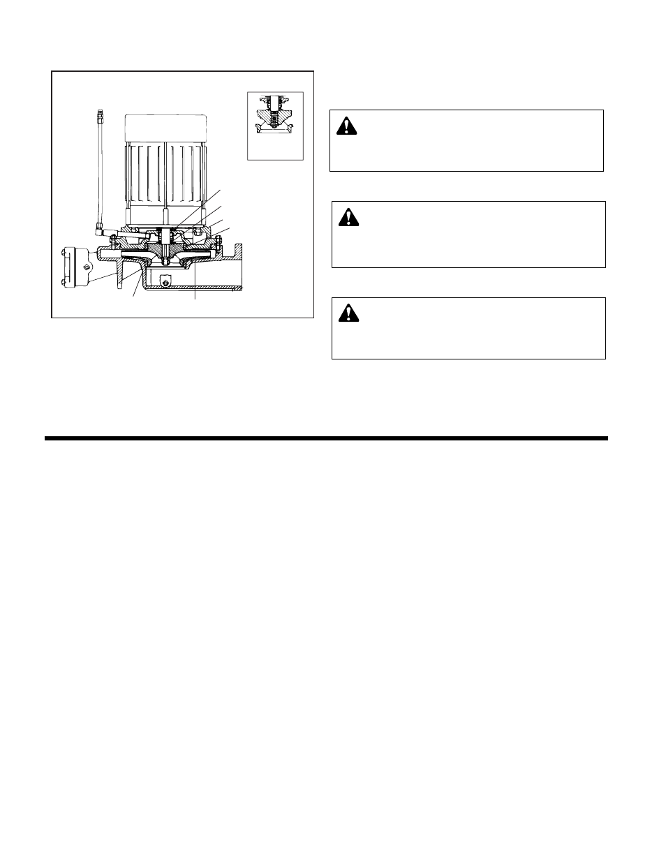
WATER
SLINGER
VIEW OF
THREADED
IMPELLER
WEAR RING
IMPELLER
2DPF03
VOLUTE
MOTOR BRACKET
MECHANICAL
SEAL
CAUTION:
DO NOT RUN DRY.
SEAL DAMAGE MAY OCCUR.
Inspect pump seal r
egularly for leaks Replace as required.
Failure to follow these instructions could result in serious
injury or death.
TROUBLESHOOTING SERIES VL UNITS
ALL UNITS ARE THOROUGHLY TESTED AT THE FACTORY BEFORE SHIPMENT AND SHOULD OPERATE SATISFACTORILY
WITHOUT FURTHER ADJUSTMENT IF PROPERLY INSTALLED AND IF NOT DAMAGED BY ROUGH HANDLING IN TRANSIT.
IF SYSTEM OR UNIT PERFORMANCE IS NOT SATISFACTORY, REFER TO THE FOLLOWING CHECK LIST.
PUMP WILL NOT START
1.
The power supply has been interrupted, disconnect switch
is open or selector switches improperly positioned.
2. Insufficient condensate accumulated to actuate float
switch.
3. Vacuum is not low enough to actuate vacuum switch.
4. Incorrect voltage for motor. Check voltage and wiring with
motor characteristics.
5. Incorrect starter for power supply.
6. The overload relays in the starter have tripped out and must
be reset. Ambient temperature may be too high.
7. Check float switch, vacuum switch or other control for
proper operation.
8. Wiring to control panel is incorrect or connections are loose.
PUMP DOES NOT RETURN ALL CONDENSA
TE TO
BOILER FEED SYSTEM (UNIT FLOODS)
1.
Pump is running backward looking down on motor.
Rotation of 3 phase motors may be corrected by inter-
changing any two of the three wires. Pump should run
clockwise.
2. Steam traps are blowing through causing condensate to
return at excessive temperatures. If 160°F is exceeded the
capacity of the pump may be reduced below its rating.
Traps should be repaired or replaced.
3. The total pressure at the pump discharge is greater than the
pressure for which the pump was designed. Check the total
pressure which includes the boiler pressure, the friction
head and the static head.
4. A valve in the discharge line between pump and boiler is
closed or throttled too tightly. Check valve is installed
backwards.
5. Condensate is held up in system periodically by induced
vacuum in boiler or radiation then released in a flood when
the pump starts. Install equalizer line.
6. The strainer is dirty thus retarding flow. Refer to instructions
for cleaning.
7. The impeller eye is clogged with trash.
8. The bellows type discharge valve fails to open. This may be
caused by the solenoid valve remaining in a closed posi-
tion, or dirt becoming lodged in the pressure release line.
Float switch failure may also cause the discharge valve to
remain shut. Replace the bellows type discharge with the
solenoid operated discharge valve. If solenoid discharge
valve has already been installed the solenoid may be stuck
shut or the float switch failed.
9. Systems with accumulator tanks should have equalizer
line run from accumulator tank to steam header: NOT
from accumulator tank to pump receiver NOR from pump
receiver to steam header. Install vacuum breaker on
accumulator tank, NOT on pump.
10. Pump is too small for the system.
11. Equalizer orifice between inlet and main compartments of
receiver is clogged.
W
ARNING: EXPLOSIBLE
Do not pr
essurize receiver. Isolate receiver during leak
test. Do not plug overflow. Do not restrict vent opening to
atmosphere. Open valves slowly. Failure to follow these
instructions could result in serious injury or death.