Bell & Gossett DN0135D Domestic Pump Vacuum Heating Units Series VL User Manual
Page 3
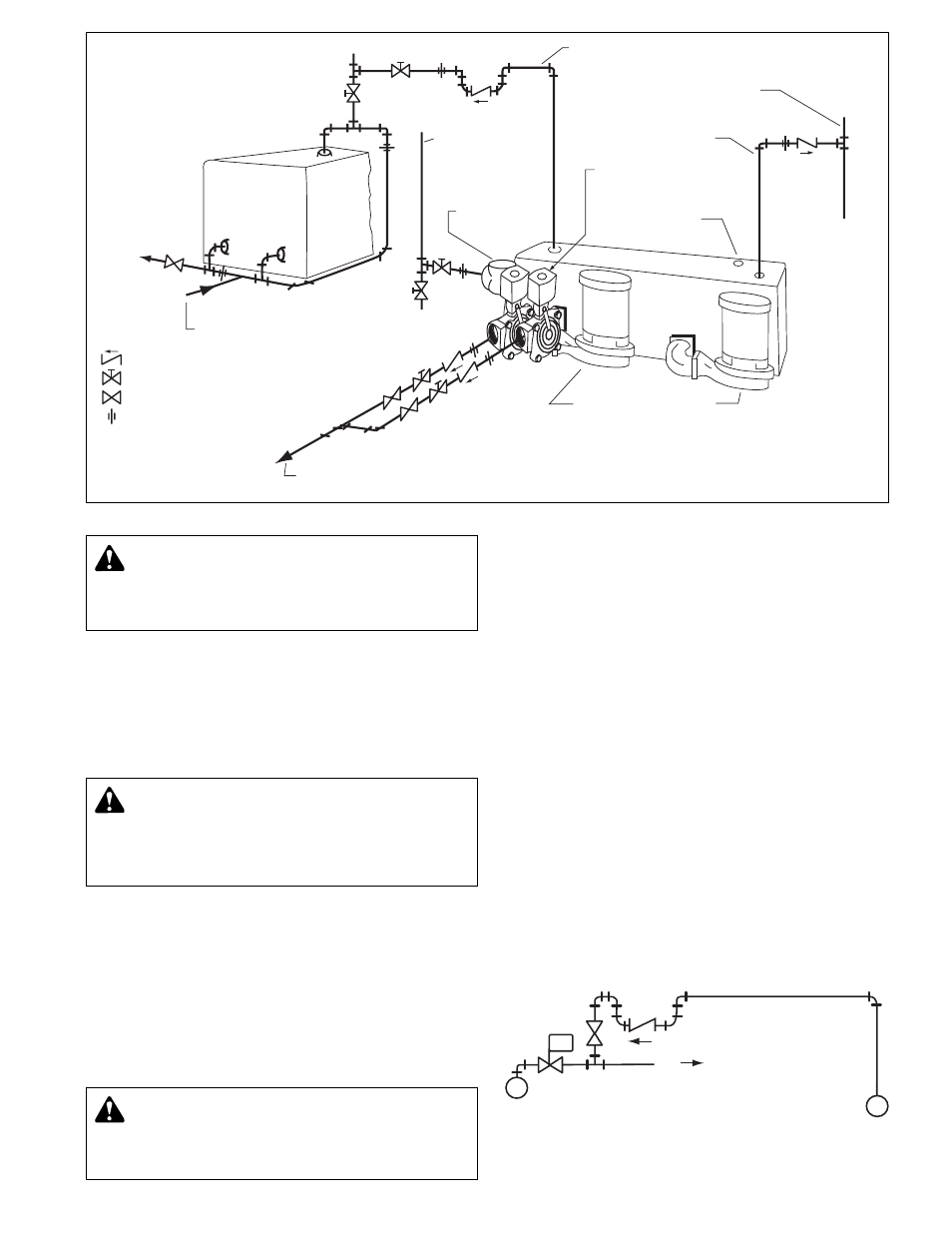
BOILER
TO
DRAIN
FROM BOILER
FEED SYSTEM
TO DRAIN
INLET
STRAINER
RETURN FROM
HEATING
SYSTEM
EQUALIZING LINE –
3
/
4
"
OPEN VENT ABOVE
BOILER WATER LINE
AIR VENT
DISCHARGE
VALVES
PRIMING
OPENING
TO DRAIN
CENTRIFUGAL PUMPS
– CHECK VALVE
– GATE VALVE
– STEAM OR PLUG COCK
– UNION
TO BOILER
FEED SYSTEM
Receivers ar
e non-code cast iron.
PRELIMINAR
Y INSPECTION
Assur
e that there is no shipping damage.
Assure that nameplate ratings agree with job specifications and
actual conditions.
HANDLING
Use car
e in installing unit.
LOCA
TION
Place unit for easy access to all parts. Allow adequate space
for servicing. Check ambient conditions.
NOTICE/TEMPERA
TURE LIMITS
Motors ar
e designed to operate in 104°F max. ambient.
Insulate or ventilate as required.
PIPING
(General)
Pipe the unit per the Elementary Piping Diagram. Locate and
support piping so as to not load the discharge valve.
PIPING (
Vent)
Install a vent pipe to atmospher
e. Pipe to be size of vent port
on unit. Do not restrict or reduce vent opening or exceed 20
feet vertical height unless an overflow connection is provided.
Series VL Units require a check valve in the vent line as shown
on the piping diagram (furnished with unit).
PRIMING POR
T
Pr
ovide a priming port as shown on piping diagram. Provide a
water supply for priming.
FLOA
T SWITCHES
Floats ar
e locked in place to prevent damage during shipment.
Remove shipping locks. Check factory settings. Floats are
adjustable for various levels of operation.
See page 7 for detailed instructions.
EQUALIZING LINE
An equalizing line must be installed with all Series VL units. This
line must be installed to prevent formation of a vacuum on the
radiation side of the system when steam stops flowing in the
mains. This vacuum may be higher than return line vacuum,
which would prevent condensate from flowing back to pump.
To correct this is an unzoned system, install equalizer line as
shown in the piping diagram. To correct this in a zoned system,
install equalizer line for each zoned section or install a vacuum
breaker on supply line on radiation side of each zone control
valve.
3
CAUTION:
UNIT LIFTING EYE
Use unit lifting eyes only to lift unit as shipped fr
om
factory. Unit must be empty and disconnected from pipes,
anchors and other restraints. Use proper rigging pro-
cedures. Failure to follow these instructions could result in
injury or property damage.
CAUTION:
NOT A CHEMICAL PUMP
Inject boiler feed compounds fr
om chemical feed tank
into boiler feed piping – never into condensate tank. Failure
to follow these instructions could result in injury or property
damage.
EQUALIZING CONNECTIONS FOR ZONED SYSTEMS
ZONE CONTROL
VALVE
STEAM MAIN
M
TO ZONE
RETURN MAIN
FIG. 3. SERIES VL PIPING DIAGRAM
WARNING: EXPLOSIBLE
Do not pr
essurize receiver. Isolate receiver during leak
test. Do not plug overflow. Do not restrict vent opening to
atmosphere. Open valves slowly. Failure to follow these
instructions could result in serious injury or death.