Floa t switch adjustment procedures – Bell & Gossett DN0135D Domestic Pump Vacuum Heating Units Series VL User Manual
Page 7
7
PROPER ADJUSTMENT OF CONTROLS RESUL
TS
IN MINIMUM CONDENSATE IN RECEIVER
CONTROLS ARE PRESET AT THE FACTORY BUT
MAY VARY DUE TO HANDLING DURING SHIPMENT.
1.
Close the inlet gate valve and, with the discharge line open,
operate the pump on “continuous” or “hand” to remove
sufficient water to lower the level to about the 7
1
/
2
inch level
in the water level gauge glass measured from the top of the
lower gauge cock. If necessary, admit water to obtain the
7
1
/
2
inch level.
2. Open the disconnect switch(es).
3a. (Units equipped with one float switch.) Adjust the cut-in
point of the float switch by depressing the float arm slightly
and adjusting the stop so that the switch turns on when the
float arm is released.
3b.(Units equipped with two float switches.) Adjust the F1, or
lead, float switch in the manner described in 3a. Admit
water to a 1" higher level and adjust the F2, or stand-by,
float switch to cut in.
4. Run pump on “float or FL and VAC” unit float switch opens
and closes the discharge valve. The discharge valve is
closed when the water level in the gauge glass no longer
drops. This level should be at approximately the four inch
level. If not, adjust the float switch.
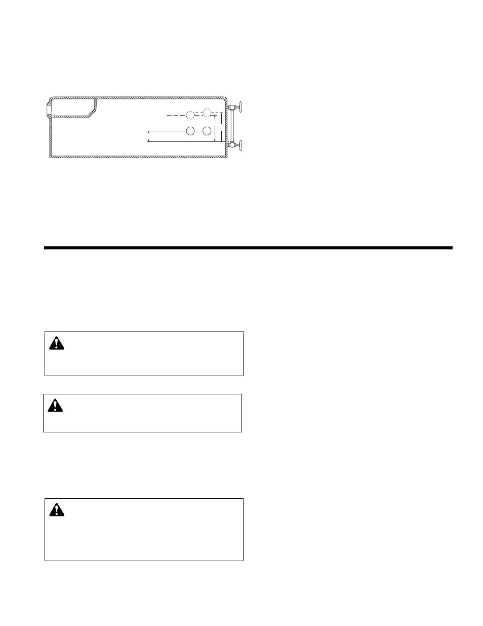
FLOA
T SWITCH ADJUSTMENT PROCEDURES
F2
F1
F2
F1
7
1
/
2
"
8
1
/
2
"
4"
HIGH LEVEL – FLOAT SWITCH(ES)
ON DISCHARGE VALVE(S) OPEN
LOW LEVEL – FLOAT SWITCH(ES) OFF
PUMP SERVICE INSTRUCTIONS FOR VACUUM PRODUCING CENTRIFUGAL PUMPS
V
ertical mounting puts motor above floor dirt and water.
Close coupled centrifugal pumps are designed for years of
trouble free service. Units have mechanical shaft seals and are
vertically mounted to put the motor above floor dirt and water.
1. Drain hurling chamber.
2. Shut-off and lock out power.
3. Make sure unit is cool enough that pump can be handled
safely. Open drain to remove remaining liquid.
4. Carefully remove pump drain plug and bleed line. Wait for
complete drainage.
5. Loosen the motor bracket to pump volute capscrews.
Assure that the pressure is relieved per caution note.
6. Complete the removal of the above hardware. Remove
pump/motor assembly and place on work bench.
7. Remove self locking stainless steel capscrews and stain-
less steel washer (or self locking brass cap nut and washer)
that secure the impeller in place.
8. To remove impeller from motor shaft proceed as follows:
(1) Keyed Shafts. Remove impeller with gear puller or other
means which will not damage impeller or bend motor
shaft.
(2) Threaded Shafts. Hold end of motor shaft opposite
pump with large screwdriver or other suitable tool and
back impeller off with a rectangular bar or other flat tool
inserted between the vanes of the impeller.
9. Remove rotating part of seal from shaft, being careful not
break carbon face.
10. Remove capscrews holding motor bracket to motor and
remove bracket.
11. Remove stationary part of seal assembly, being careful not
to chip or break ceramic seal.
12. To install seal proceed as follows:
(1) Clean recess in bracket thoroughly. Coat recess and
“rubber” portion of seat with soap solution. Press seat
into recess firmly by hand making certain both parts
bottom evenly. If seal cannot be bottomed with fingers
place cardboard shipping disc on ceramic and force into
place with tool.
(2) Carefully place bracket in position on motor shaft
without displacing ceramic seat and secure bracket to
motor with capscrews.
CAUTION:
PRESSURIZED SYSTEM
Operating system may contain very hot water
. Close
inlet and open drains before servicing. When servicing,
loosen scr
ews and move components to assure pressure is
relieved before
r
emoving
scr
ews. Keep drains open during
servicing. Failure to follow these instructions could result in
injury or death.
CAUTION:
HOT SURFACE
Surfaces ar
e hot when system is in operation. Do not
touch hot receiver, let unit cool before servicing. Failure to
follow these instructions could result in serious injury or
death.
W
ARNING: HIGH VOLTAGE
Disconnect and lock out power befor
e connecting
servicing unit. Failure to follow these instructions could
result in serious injury or death.