Description and inst allation – Bell & Gossett DN0135D Domestic Pump Vacuum Heating Units Series VL User Manual
Page 2
2
DESCRIPTION AND INST
ALLATION
The Series VL vacuum heating units ar
e designed to serve the
dual purpose of pumping accumulated condensate back to the
boiler feed tank and maintaining vacuum in the condensate
system. This vacuum will draw air out of the system on start-up
and facilitate the flow of steam thru the heating system.
One pump/vacuum producer/discharge valve assembly
controls both the condensate discharge and the production of
vacuum. Two pump (duplex) units have a second assembly for
backup and to provide extra capacity to handle peak loads.
Various electrical controls are offered to meet system require-
ments. These controls are normally supplied as part of the
assembled unit and a wiring diagram is furnished with the unit.
Refer to this electrical diagram as required.
The units respond to both changing condensate levels and
system vacuum requirements.
In operation the centrifugal pump circulates water (condensate)
thru the multi-jet nozzle creating multiple jets of water entering
the venturi. These jets entrain air and gasses creating a smooth
steady vacuum in the nozzle body and in the condensate
system. The air and gasses are separated in the receiver and
vented to atmosphere.
Low system vacuum or high water in the receiver will start the
pump to create vacuum and circulate water.
The solenoid operated discharge valve is opened in response
to the condensate level float switch. Controlled opening of the
discharge valve holds sufficient back pressure in the nozzle
body that the vacuum producer continues to function even
when discharging condensate (simultaneous rating).
When the vacuum and float switches have been satisfied and
the pump stops, the check valve in the nozzle body closes,
preventing the return of air and water to the system.
An internal orifice permits the vacuum in the receiver and in the
system to slowly equalize. Note that the vent line on the Series
VL requires a check valve to prevent return of atmospheric air
to the receiver. Without the check valve and orifice, a system
could develop high vacuum upon cooling holding the check
valve closed and thereby preventing flow of condensate into
the unit.
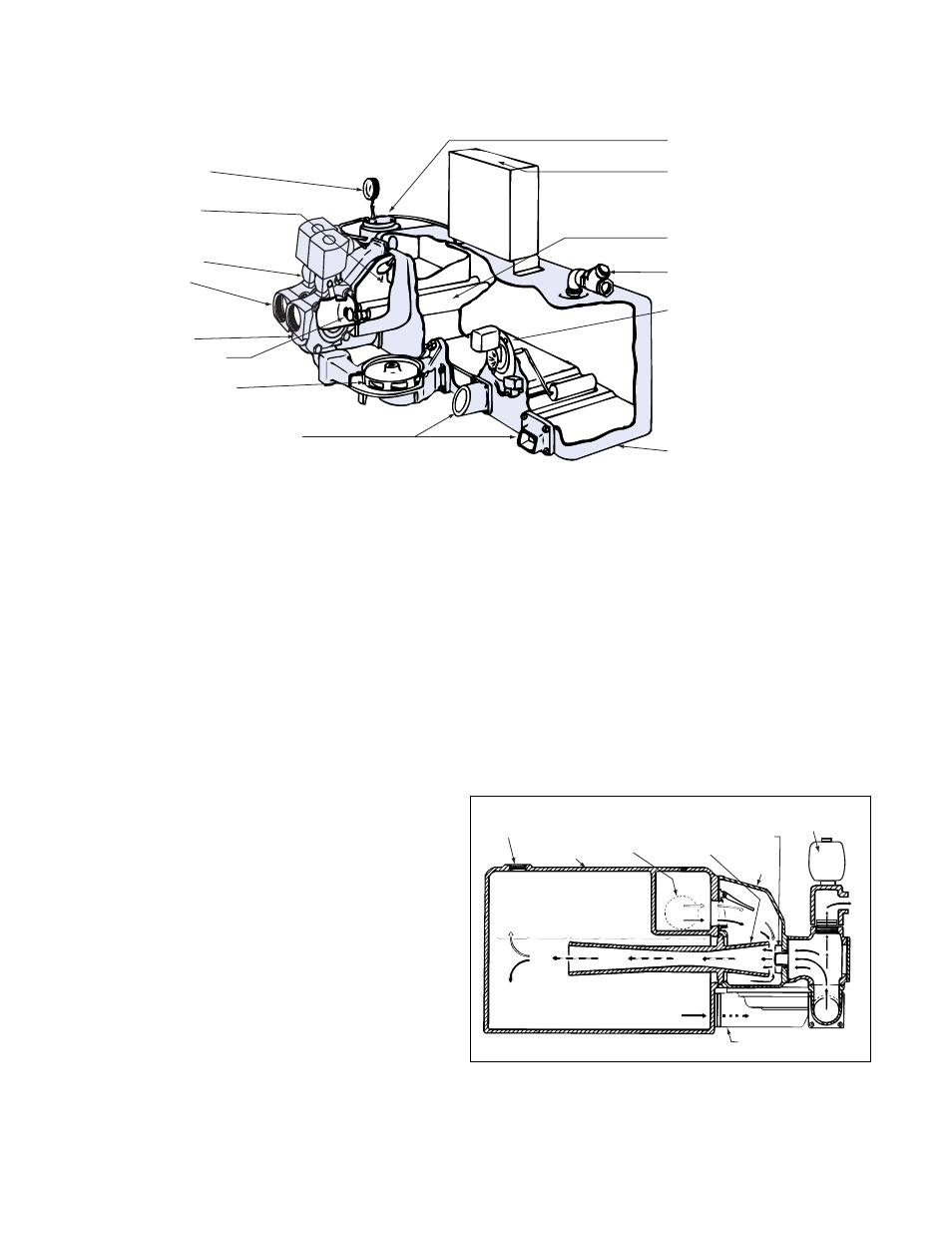
STRAINER
CONTROL PANEL
VENTURI
AIR VENT VALVE
FLOAT SWITCH
RECEIVER
MOUNTING PADS FOR DUPLEX
CENTRIFUGAL PUMPS
CENTRIFUGAL PUMP
MULTI-JET NOZZLE
DISCHARGE
MANIFOLD
SOLENOID
DISCHARGE VALVE
DISCHARGE
CHECK VALVE
VACUUM GAGE
DSK-1330
FIG. 1 SERIES VL
VACUUM UNITS 25,000-60,000 EDR
FIG. 2
SERIES VL VACUUM PRODUCER
AIR VENT
RECEIVER
INLET
MULTI-JET NOZZLES
VENTURI
NOZZLE
BODY
CENTRIFUGAL PUMP
DSK-1328
SOLENOID
DISCHARGE
VALVE