Xylem AC2008B Series HSC3 Base Mounted Centrifugal Pump User Manual
Page 21
21
14. Lubricate and roll the O-rings into the groove in each
stuffing box.
NOTE: At this point reassemble the rotating element by
starting on the outboard end first (the end opposite the
coupling) as this end locates the settings of the mechani-
cal seal.
IMPORTANT: Steps 11 through 21 must be completed,
on the outboard end, within 10 to 12 minutes to assure
proper placement of the mechanical seals.
15. Lightly coat the outboard end of the pump shaft with P-80
Rubber Lubricant Emulsion, vegetable oil, or equal and
slide the mechanical seal head onto the shaft. (See Photo
11)
16. Slide the stuffing box, with the gland plate, fully on the
shaft, being very careful that the head and seat of the
mechanical seal do not get damaged. COMPRESS THE
SEAL SPRING ONLY AS FAR AS REQUIRED TO INSTALL
THE BEARINGS. (See Photo 12)
17. Fill lip seal cavity with approximately .50 ounces of
grease.
18. Heat the ball bearings using dry heat to 10% – 15%
soluble oil and water, or an induction heater.
CAUTION: DO NOT EXCEED A TEMPERATURE OF 275°F.
19. Using gloves, slide the heated bearing onto the shaft
against the shaft shoulder. (See Photo 5 on page 18)
20. Install the locknut and lockwasher on the outboard end of
the shaft. Make certain that the locknut is secure and
bend over the tabs on the lockwasher. (See Photo 6 on
page 18)
21. Allow the bearing to cool to room temperature. Coat the
exposed sides of the bearing with two or three ounces of
recommended grease.
22. Coat the inside of the bearing housing with grease and
slide it into place over the bearing. Attach the bearing
housing to the stuffing box with the capscrews.
23. Repeat steps 15 through 22 for the inboard end.
IMPORTANT: Steps 15 through 25 and must be com-
pleted within 10 to 12 minutes to assure proper place-
ment of the mechanical seal.
NOTE: A locknut and lockwasher are not installed on the
inboard end of the pump shaft.
24. Reinstall the coupler on the end of the shaft.
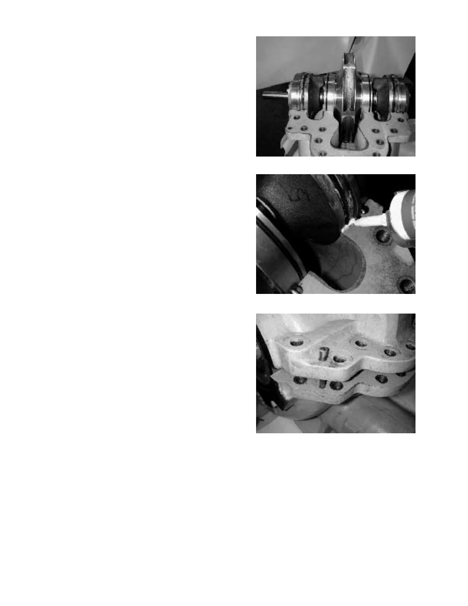
25. Set the rotating element in the pump casing, assuring cor-
rect rotation. Locate both stuffing box tongues in their
respective casing grooves. Locate the pins in the stuffing
box and the casing wear rings in their respective slots at
the casing parting surface. Correct any O-ring bulging.
(See Photo 13)
CAUTION: DO NOT CUT OR DAMAGE THE O-RINGS
WHEN LOWERING THE ROTATING ELEMENT INTO
POSITION. WHEN ALL FOUR ANTI-ROTATION PINS
ARE LOCATED CORRECTLY, THERE WILL BE SOME
CASING RING LOOSENESS.
26. Apply a small bead of Dow Corning RTV silicone sealant
or equal at the parting line on top of gasket at the stuffing
box O-rings. (See Photo 14)
27. Locate the upper half of the casing into place using the
tapered dowel pins and install the casing main joint bolts
(See Photo 15). The casing joints should be tightened to
the following torques: 140 ft.-lb. minimum for
5
/
8
"-11
hex head cap screws (Grade 5); 350ft.-lb. minimum for
7
/
8
"-9 Ferry Cap Counterbore screws (Grade 8). Bolt
torquing pattern is shown in Illustration 9 on page 12.
NOTE: Torque values are essential in obtaining proper
gasket compression so no leakage can occur at the main
joint.
28. Rotate the shaft by hand to assure that it turns smoothly
and it is free from rubbing or binding.
29. Assemble the coupler and check alignment, following the
instructions on page 7. Replace the coupler guard.
Photo 13 – Rotating element inside casing
Photo 14 – Addition of sealant
Photo 15 – Casing mainjoint