Xylem AC2008B Series HSC3 Base Mounted Centrifugal Pump User Manual
Page 17
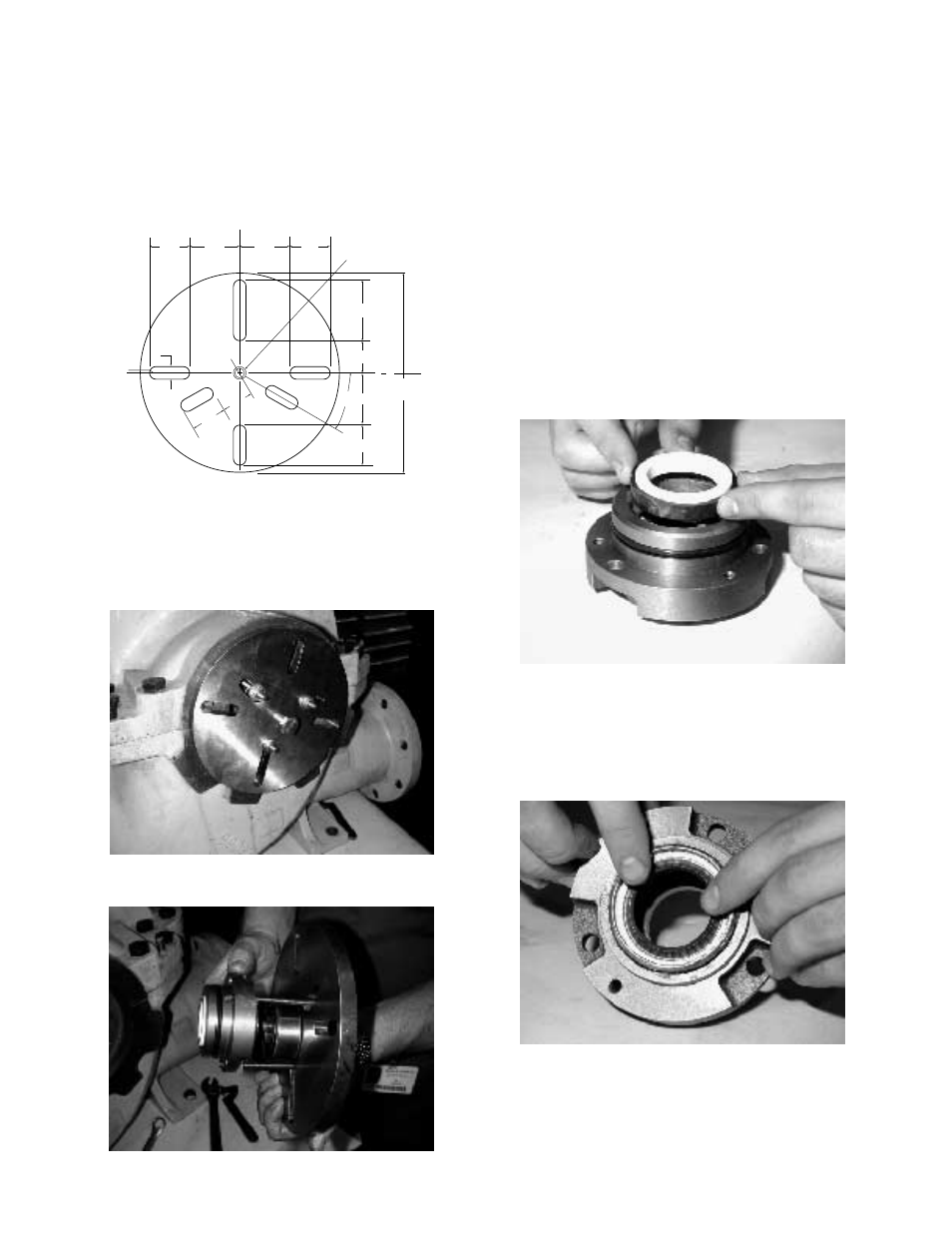
6. Insert threaded rods into the tapped holes in the gland
plate and install a fixture on the threaded rods to use a
puller. (See Illustration 10 for Dimensions of Universal
Fixture PN: AC2394) Using the puller, tighten the bolt in
the center of the fixture to remove the bearing and gland
plate from the shaft. (See Photos 1 and 2).
CAUTION: FAILURE TO REMOVE THE SOCKET-HEAD
CAPSCREWS BEFORE TRYING TO PULL THE BEAR-
INGS OFF COULD CAUSE DAMAGE TO THE PUMP.
7. Remove the inboard bearing and gland plate in the same
manner.
NOTE: The locknut and lockwasher are not used on the
inboard bearing.
CAUTION: DO NOT REUSE THE BALL BEARINGS.
8. Remove the mechanical seal head from the pump shaft.
NOTE: To ease in the removal of the mechanical seal
heads, you may want to use 2 allen wrenches as hooks or
form hooks from wire.
9. Drive the lip-seals, the mechanical seal seats, from each
of the gland plates by tapping on them from the rear.
10. Remove the O-rings from each of the gland plates.
Assembly of the Mechanical Seals and Bearings
without removing the Upper Half of the Casing
NOTE: All bearings, O-rings, and lip-seals should be replaced
with new parts during assembly. All usable parts should be
cleaned of foreign matter before reassembly.
NOTE: Reassemble the pump by starting on the outboard end
(the end opposite the coupling). This end locks the rotating
element into position in the casing.
1. Press the stationary mechanical seal seat into the gland
plate until it bottoms out against the bore. Lightly lubri-
cate the bore to ease assembly. (See Photo 3)
2. Press a new lip seal into the gland plate. Before installing
the lip seal, lubricate the lip-seal with lightweight oil. Note:
Lip seals should sit against machined shoulder in the
gland plate. The lip seal should face away from the
mechanical seal seat. (See Photo 4)
1.75"
1.75"
2.0"
2.0"
.437 Ø DRILL THRU
FOR .500-13
UNC-2B THREAD
2.44"
1.25"
1.75"
2.0"
30
∞
TYP
1.38"
1.25"
TYP
.25R
.50 TYP
8.0" Ø X .50 THK MIN.
H.R. STEEL
17
Illustration 10 – Dimensions for Universal Fixture (PN: AC2394)
Photo 1 – Removal of bearing and
gland plate using universal fixture
Photo 3 – Assembly mechanical seal seat into gland plate
Photo 4 – Assembly of lip seal into the gland plate
Photo 2 – Gland plate and bearing removed from stuffing box