Service instructions for an hsc, Pump, Standard mechanical self flushing seal – Xylem AC2008B Series HSC3 Base Mounted Centrifugal Pump User Manual
Page 16
SERVICE INSTRUCTIONS
FOR AN HSC
3
PUMP
To Replace the Mechanical Seals and Bearings
without removing Upper Half of the Casing
NOTE: In order to replace the mechanical seal and bearing
housing on the coupler end, you must use a spacer type
coupler.
1. Close valves on suction and discharge sides of pump. If
no valves have been installed, it will be necessary to drain
the system.
2. Remove the coupler guard. For spacer coupler, loosen the
capscrews which secure the coupler flanges to the
coupler hubs. Remove the coupler flanges and sleeve by
compressing the flanges and pulling out from beneath the
hubs or by loosening the allen set screws and sliding the
hubs back on the shafts. Remove the coupler hubs from
the pump shaft. For non-spacer couplers, loosen set
screws and slide flanges back on shafts and remove
rubber element.
3. Remove the capscrews from each of the bearing housings
and remove the bearing housings by placing two 2.0"
long full-threaded capscrews or allen set screws in the
jackscrew holes provided.
4. Bend back the lockwasher tab and remove both the lock-
washer and locknut from the outboard end of the shaft
(the opposite side of the coupling).
5. Remove the socket-head capscrews holding the gland
plates to the stuffing boxes.
16
CAUTION: Extreme Temperature Hazard
Allow pump temperatures to reach acceptable levels
before proceeding. Open drain valve. Do not proceed until
liquid stops coming out of drain valve. If liquid does not
stop flowing from drain valve, isolation valves are not seal-
ing and should be repaired before proceeding. After liquid
stops flowing from drain valve, leave drain valve open and
continue. Remove the drain plug located on the bottom of
the pump housing. Do not reinstall plug or close drain
valve until reassembly is completed. Failure to follow these
instructions could result in property damage and/or moder-
ate personal injury.
WARNING: Unexpected Start-up Hazard
Disconnect and lock out power before servicing.
Failure to follow these instructions could result in serious
personal injury or death and property damage.
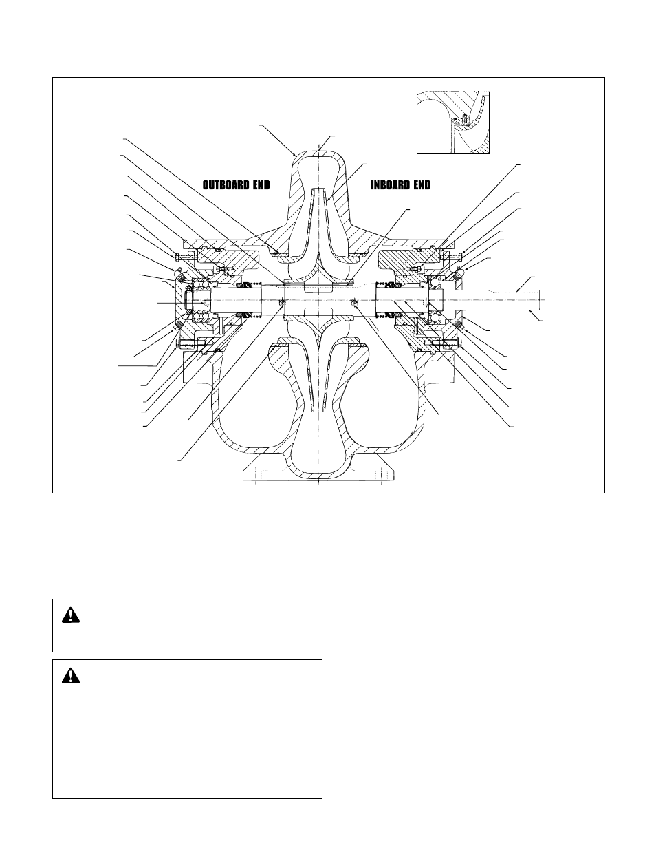
IMPELLER
IMPELLER KEY
PIPE PLUG
GLAND PLATE
SOCKET HEAD
CAP SCREW
STUFFING BOX
BEARING HOUSING
JACK SCREW
LIP SEAL
INBOARD
BEARING
GREASE FITTING
COUPLING KEY
SHAFT
BEARING HOUSING
STUFFING BOX
DOWEL PIN
SUCTION SIDE
CASING GASKET
DISCHARGE SIDE
CASING GASKET
CASING RING
DOWEL PIN
CASING RING
“O” RING
MECHANICAL
SEAL
GLAND PLATE
STUFFING BOX
BEARING
LOCK WASHER
BEARING HOUSING
CAP SCREW
BEARING LOCKNUT
BEARING
HOUSING
STUFFING BOX
DOWEL PIN
OUTBOARD
BEARING
GREASE FITTING
BEARING HOUSING
JACK SCREW
LIP SEAL
GLAND PLATE
“O” RING
STUFFING BOX
“O” RING
IMPELLER
SNAP RING
CASING RING
CASING
PIPE PLUG
PIPE PLUG
BEARING HOUSING
CAP SCREW
CASING RING
DOWEL PIN
Impeller Wear Ring
Impeller Rings can be
added — Optional extra.
Standard Mechanical Self Flushing Seal
HSC
3
Cross-Section