Xylem AC2008B Series HSC3 Base Mounted Centrifugal Pump User Manual
Page 19
5. Tap the stuffing boxes with a soft-headed hammer to
break the seal between the stuffing box and lower casing
half, and lift the rotating element out of the lower casing.
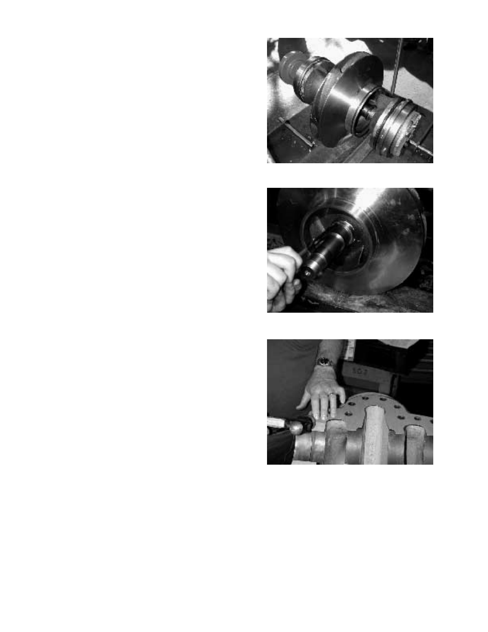
Rotating element may be removed to a suitable location
for repair.
NOTE: A spare rotating element can be installed at this
point. (See Photo 7)
6. Remove the capscrews from each of the bearing housings
and remove the bearing housings by placing two cap-
screws in the jackscrew holes provided.
7. Bend back the lockwasher tab and remove both the lock-
washer and locknut from the outboard end of the shaft
(the opposite side of the coupling).
8. Remove the capscrews holding gland plate to the stuffing
box.
9. Insert threaded rods into the tapped holes in the gland
plate and install a fixture on the threaded rods to use as a
puller. (See Illustration 10 on page 17, for dimensions of
Universal Fixture). Using the puller, tighten the bolt in the
center of the fixture to remove the bearing and gland plate
from the shaft. If the bearing does not come off the shaft,
insert a spacer between the center bolt and the shaft, and
retighten the bolt. Remove the inboard bearing and gland
plate in the same manner. (See Photos 1 and 2 on page 17)
NOTE: The locknut and lockwasher are not used on the
inboard bearing.
10. Remove the gland plates from the stuffing boxes and
remove the O-rings from the stuffing boxes.
CAUTION: DO NOT REUSE THE BALL BEARINGS.
11. Remove the mechanical seal head from the pump shaft.
12. Drive the lip-seals, the mechanical seal seats, from each
of the gland plates by tapping on them from the rear.
13. Remove the O-rings from each of the gland plates.
14. Remove the two casing rings from the impeller and
remove the O-rings from each of the casing rings.
15. Remove the impeller-retaining ring with retaining pliers.
(See Photo 8). Heat the impeller hub on both ends to
350°F maximum, and pull or push the impeller from the
shaft. (Instead of heating the impeller, you may press
impeller off the shaft, if press is available.)
NOTE: Press away from the coupling end.
NOTE: For impellers with replaceable rings; remove the
rings, if necessary, by cutting with a cold chisel.
16. Remove the impeller key from the shaft.
19
Photo 7 – Rotating element
Photo 8 – Removal of impeller retaining ring
Photo 9 – Trimming casing gasket