Xylem IM125 R02 RJA & RJDS Quick Set User Manual
Page 4
NOTE: As the horizontal distance and the pipe size increase, the length of time to prime increases.
TABLE B — PIPE SIZES FOR HORIZONTAL RUNS
Section 1
Installing a New Shallow
Well
If you are replacing an existing shallow well pump, refer to
Section 2.
Fittings for a shallow well installation such as
foot valves, well adapters, couplings, unions and piping
must be purchased separately. Your Red Jacket Jet pump
can be adapted horizontally to shallow well or drive
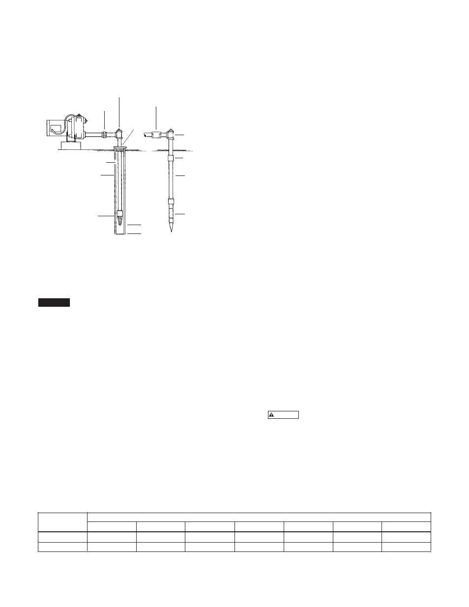
point systems. See Figure 2.
INITIAL PIPING IN A SHALLOW WELL
Step 1. To insure continual priming on a shallow well sys-
tem, (Left-Figure 2) a foot valve must be installed. On a drive
point system, (Right-Figure 2) a check valve must be installed
as close as possible to the pump. Examine the foot valve or
check valve to see that it is clean and seated properly.
Step 2. Inspect the piping to be sure it is free of obstruc-
tions such as dirt. Galvanized iron pipe is often used, but
plastic pipe can be used if allowable under existing state
and local plumbing codes. Use either non-toxic pipe sealing
compound or tape on male thread joints of galvanized pipe
(tape or cement on plastic pipe) to facilitate making air
tight joints.
Step 3. To install the suction drop pipe in an existing shallow
well, support the pipe with a pipe holder or clamp. Fill each
pipe section with water when lowering, constantly observing
for leaks. Install the foot valve no closer than 2' from the bot-
tom of the well to prevent sand, mud, or other foreign matter
from clogging the intake.
Step 4. Horizontal piping from the pump to the well should
be as short as possible to avoid increased friction losses.
For most efficient operation, the suction pipe should not
be smaller than the suction tapping on the pump. Table B
shows the correct pipe sizes for horizontal runs. If the pump
is being installed offset from the well, the piping should pitch
upward from the well to the pump about 1" for each 10' of
pipe to prevent air pockets in the line. Plumbing should be
below the frostline or otherwise protected from freezing.
Step 5. Attach appropriate tee or adapter at the junction of
the horizontal and vertical suction pipes as shown in Figure
2. The tee can be used to clean the well.
Step 6. It is important to clean the well of sand and muddy
water to prevent damaging your pump. Clean the well by in-
serting a garden hose down the well pipe and surging water
into the well. Wait until the water flowing out of the suction
pipe is clean.
Section 2
Installing or Replacing a
Shallow Well Pump
TYPICAL INSTALLATIONS
In order to eliminate unnecessary down time in your water
supply, take a few minutes before you start the installation to
study your existing piping system and the typical Red Jacket
system layouts shown in Figure 3. In some cases additional
piping may be necessary. If you are replacing a conventional
pressure tank with a pre-charged air tank, the air volume con-
trol line is not necessary. Note in the illustrations how your
Red Jacket pump may be piped from either the top or side.
Step 1.
FOR YOUR SAFETY turn off the electri-
cal power supply at the service entrance before connect-
ing or disconnecting any wiring to the pump to avoid any
possible electrical shock hazard.
Step 2. Drain the holding tank. Also disconnect the suction
pipe, the service line, and if necessary, the air volume control
line. Remove old pump.
FIGURE 2
UNION
TEE
WELL
ADAPTER
SUCTION DROP PIPE
WELL CASING
FOOT
VALVE
SHALLOW
WELL
SYSTEM
CHECK VALVE
TEE
HEAVY DUTY
DRIVE PIPE COUPLING
DRIVE PIPE
OR SUCTION PIPE
DRIVE
POINT
SYSTEM
WELL OR
SAND POINT
2' MINIMUM
NOTICE
WARNING
4
Pump
Suction
Size
10-50 ft.
51-75 ft.
76-100 ft.
101-150 ft.
151-200 ft.
210-250 ft.
251-300 ft.
½ & ¾ HP
1¼
1½
1½
2
2
2
2
1 HP
1½
2
2
2½
2½
2½
2½