Inspection & replacement – Xylem A-C Fire Pump – Vertical Turbine Fire Pump AC8499 User Manual
Page 21
21
Inspection & Replacement
1. Clean all pump parts thoroughly with a suitable cleaner.
2. Check bearing retainers for deformation and wear.
3. Check shafts for straightness and excessive wear on bear-
ing surfaces. Check deflection of shafts, average total
runout shall not exceed 0.005" (0.13mm) T.I.R. for every 10
feet (3m) of shaft length.
4. Visually check impellers and bowls for cracks and pitting.
Check all bowl bearings for excessive wear and corrosion.
5. Replace all badly worn or damaged parts with new parts.
In addition, replace all gaskets and packing as required.
TURBINE BOWL WEAR RING INSTALLATION
1. Place chamfered face of the bowl or impeller wear ring
towards the ring seat and press the ring into the seat. Use
an arbor press or equal, making sure the ring is flush with
the edge or the wear ring seat.
BOWL, SUCTION BELL AND
LINESHAFT BEARING INSTALLATION
1. Press bearing (653) into retainer (652) using an arbor press
or equal.
2. Press bearing (690) into suction bell (689) using an arbor
press or equal.
3. Press bearings (672) into intermediate bowl (670) and
beaing (664) into discharge bowl (669). Place the bowl with
the flange downward and press bearing through cham-
fered side of bowl hub until the bearing is flush with the
hub using an arbor press or equal.
TAPER COLLET CONSTRUCTION BOWL ASSEMBLY
1. For ease in reassembly apply a thin film of turbine oil to all
mating and threaded parts.
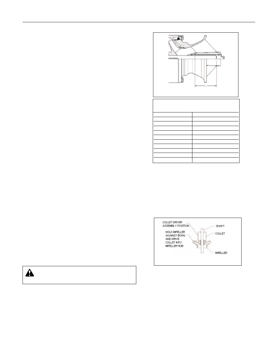
2. If the sand collar is not assembled to the shaft, install the
sand collar. The sand collar is attached to the shaft with a
shrink fit. The larger diameter of the counterbore of the
sand collar goes toward the suction bell bearing. Heat the
sand collar until it slips over the shaft and quickly position
it so that the bottom of the sand collar is set according to
the "X" dimension, before it cools. See Figure 10. See
Table 1 for the "X" dimensions. Slide the pump shaft into
the suction bell bearing until the sand collar rests against
the suction bell.
3. Hold the shaft in this position by inserting a capscrew with
an assembly jig into the hole in the end of the suction bell
and then into the threaded hole in the end of the shaft.
4. Slide the first impeller over the shaft until it seats on the
suction bell.
5. Insert a screwdriver into the slot in the taper collet (677)
spread the slot and slide the collet over the pump shaft.
Hold the impeller against bowl and slide the collet into the
impeller hub.
6. Hold shaft with capscrew and washer against the suction
bell and drive the taper collet into place with a collet driver,
(See Figure 11). After collet is in place, recheck "X" dimen-
sion (Table 1).
7. Slide intermediate bowl (670) onto shaft and secure with
capscrews provided.
8. Repeat preceding procedure for number of stages
required.
9. Remove capscrew and washer and check that the shaft
rotates freely without dragging or binding. Also check for
adequate lateral end play.
Figure 11
Figure 10
Pump Shaft Set Up
Dimensions
Pump Model
"X" Dim.
10WALC
5.19"
11CLC
4.88"
11CHC
4.88"
12CHC
5.31"
14RJHC
5.06"
14RHHC
7.13"
16DMC
5.88"
18DMC
7.56"
18DHC
7.56"
20EHC
7.00"
Table 1
WARNING
: Wear protective gloves and use appro-
priate eye protection to prevent injury when handl-
ing hot parts.