Installing the column – Xylem A-C Fire Pump – Vertical Turbine Fire Pump AC8499 User Manual
Page 12
12
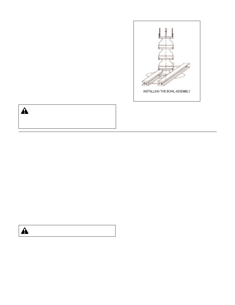
2. Place two I-beam supports across the base plate opening,
strong enough to safely support the weight of the entire
pump assembly. These I-beams should be connected by
threaded rods and nuts, so as to clamp them firmly together
for the portion to be supported. (See Figure 4).
3. Put in place a suitable hoist or derrick over base plate
opening. Place the elevator clamps just below the dicharge
bowl flange or install two threaded eye bolts through bolt
holes in flange 180º apart.
4. Attach sling to elevator clamps or eye bolts and hoist into
position over foundation opening (See Figure 4).
5. Carefully lower bowl assembly, guiding the unit so it does
not strike the sides of the opening. Continue to lower bowl
assembly until the elevator clamps or discharge bowl
flange rests firmly on the I-beam supports.
6. Place a cover over the discharge bowl opening to prevent
entrance of dirt or other foreign matter.
Figure 4
Installing the Column
OPEN LINESHAFT
Pump lineshafts are connected with threaded couplings.
When provided, see the Certified Pump Outline Drawing for
the number of column and shaft sections required:
1. Check the headshaft (608) and lineshaft (646) for straight-
ness. Average total runout should be less than 0.0005" TIR
(0.013 mm) per foot (0.305 m), not to exceed 0.005" T.I.R.
(0.127 mm) for every 10 feet (3 m) of shafting.
2. Apply a thin film of oil to lineshaft (646) and coupling (649)
threads (in non-galling material, or Molykote if galling
material). Start threads manually until resistance is felt. A
fine wire inserted in the drill hole at the center of the cou-
pling can be used as a gauge to determine when the cou-
pling is correctly positioned on the shaft. Run the upper
lineshaft into the coupling until it is hand tight. Remove the
wire after installing the coupling. Complete the joint using a
pair of pipe wrenches, one on the top of pump shaft (660)
and the other on the coupling (649).
3. Use chain wrenches (clamp type) attached to the shaft to
tighten the two shafts, using care not to damage any bear-
ing journal areas. NOTE: Shaft threads are left-handed.
4. Hoist column section over bowl assembly. Lower column
over lineshaft until column flange engages the discharge
bowl. Manually thread the column into the discharge bowl.
Complete joint by tightening column with chain tongs until
the end of the column butts firmly against discharge bowl.
5. For flanged column, install two eyebolts diametrically
opposite the upper flange of the bottom volume. Attach a
sling to the eyebolts and to the hoist hook.
Lower column section until the flange engages the flanged
top bowl register. Insert as many bolts through both
flanges as possible. Lift column assembly high enough to
allow rotation of the supports. Install and tighten remaining
capscrews gradually in diametrically opposite pairs until all
are uniformly tight.
6. Lift the assembly and remove the elevator clamp or sup-
ports and slowly lower the bowl and column assembly.
Place supports on the base plate and continue to lower the
assembly until the column elevator clamps or colum flange
comes to rest on the supports. Place an elevator clamp
under the column pipe and allow it to butt firmly against
the column pipe coupling
7. Place the bearing retainer over the shaft and locate it in the
column coupling recess.
Flanged columns will normally have separate bearings
retailers, which will fit into the female registers in the
flanges on both ends of the column. Large flange column
will have the bearing retainer integral with the column. The
top flange of the column will have a male register and the
bottom flange of the column will have a female register.
For metal bearings, pour a small amount of oil between the
bearing and shaft. Install threaded coupling on protruding
end of lineshaft.
8. Repeat the preceding procedures until all column sections
required have been installed. For deeper set pump units, a
stub shaft will be the top shaft.
CAUTION
: Do not drop any foreign object into the
bowl assembly. Such an object can cause serious
damage to the pump and any downstream components
Any foreign object dropped into the bowl assembly must be
retrieved prior to continuing assembly.
CAUTION:
Use "MOLYKOTE" Dow-Corning or equal
for all galling material such as 316 stainless steel.