Installing the driver – Xylem A-C Fire Pump – Vertical Turbine Fire Pump AC8499 User Manual
Page 14
INSTALLATION OF A HOLLOW SHAFT DRIVER
This refers to either VHS type electric motors or hollow shaft
type gear drives.A small paragraph will be devoted to combi-
nation electric motor and right angle gear drives.
NOTE
: When pump is supplied with a thrust pot, do not
secure driver to discharge head until after the thrust pot and
flexible coupling are installed.
1. The driveshaft projecting through the quill or hollow-shaft
of the driver is separate from the pump shaft and con-
nected to same by a rigid flanged coupling or threaded
coupling.
2. Driver support. When a driver support is furnished and not
installed, proceed as follows:
A. Hoist driver support, inspect the mounting surfaces,
register, and clean these surfaces thoroughly.
B. Install driver support on discharge head and secure with
capscrews provided.
3. Attach a sling to the lifting lugs of driver, hoist motor,
inspect the mounting surface, register, and shaft exten-
sion, and clean these surfaces thoroughly. If any burrs are
found, remove burrs with a smooth mill file, cleaning thor-
oughly afterward.
4. Orient the motor conduit box in the required position. Align
the motor mounting holes with the mating tapped holes on
the discharge head. Lower the motor until the registers
engage and the motor rests on the discharge head. Secure
motor with capscrews provided.
5. On drivers having a non-reverse ratchet or pins, manually
turn the driver shaft clockwise viewed from the top until the
non-reverse ratchet or pins fully engage.
6. Lubricate motor bearings in accordance with instructions
given on lubrication plate attached to the motor case.
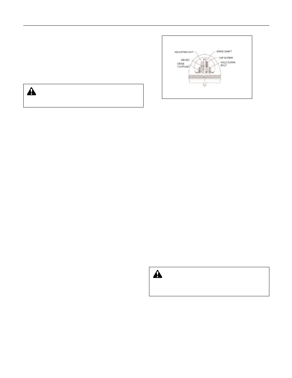
7. The driving mechanism of all hollow shaft drives is shown
on Figure 6. The driveshaft (606) extends up through the
quill or hollow shaft of the motor (or gear drive) and is held
in place by an adjusting nut (604), which not only carries
all the static and hydraulic thrust of the impellers and
shaft but also provides the adjustment for the impeller
clearances.
8. After lowering and orienting the motor and/or gear drive as
explained above, remove the drive coupling and the hold
down bolts as shown in Figure 6.
9.
Screw the adjusting nut (604) loosely onto the end of drive-
shaft (606). Clean thoroughly and attach a light line below
the nut. Lower the driveshaft through the motor quill
shaft. Examine closely for dirt or burrs between shaft
ends.
10.
Apply a suitable thread compound to the driveshaft
threaded coupling. Thread the driveshaft into the threaded
coupling and tighten.
COMPLETION OF INSTALLATION OF A
HOLLOW SHAFT DRIVER
1.
Remove lifting sling and see if driveshaft centers inside
the motor quill shaft within 0.06" (1.5mm). If it does not,
misalignment is indicated.
2.
Any driveshaft misalignment with driver quill shaft could
be caused by a bent driveshaft, burrs, or foreign matter
between shaft ends or any of the mounting flanges:
motor to mount, mount to discharge head, discharge
head mounting to plate or the plate itself could be out of
level. If the latter, shimming between it and discharge
head base, will correct it. Also, check concentricity of
motor to motor stand to discharge head.
3.
With the motor in place and the driveshaft projecting
through the motor quill shaft, connect up the electricity
and check motor rotation. This should be counter-
clockwise when viewed from the top. See arrow on pump
name plate. If motor does not rotate counter-clockwise,
you can change the rotation by interchanging any two
leads (for three phase only, for single phase motors see
motor manufacturer’s instructions.)
4.
Install motor drive coupling, inserting the ratchet pins if a
non-reverse ratchet is used. Match the coupling lugs with
corresponding holes in motor. Tighten down hold down
bolts evenly, making sure drive coupling is properly
seated in the register fit.
14
Installing the Driver
Figure 6
WARNING:
Do not work under a heavy suspended
object unless there is a positive support and safe-
guards which will protect personnel should a hoist or sling
fail.
CAUTION:
Never check motor rotation with the
drive coupling in place. The bore clearance between
the drive coupling and the pump shaft O.D. is so close that
should the motor spin with this shaft stationary, galling and
locking together is very likely to take place.