Disassembly – Xylem A-C Fire Pump – Vertical Turbine Fire Pump AC8499 User Manual
Page 20
20
Section 6 - Disassembly & Reassembly
Disassembly
NOTE
: Pump components should be match-marked prior to
disassembly to ensure they are reassembled in the correct
location.
HEAD AND COLUMN
1. On pumps which are driven through a gear drive, remove
the driveshaft between the gear and the prime mover.
2. On pumps, which are electric motor driven, remove the
electrical connections at the conduit box and tag the elec-
trical leads, so they can be reassembled the same way
they were disassembled.
3. Uncouple driver (or gear box) from pump shaft and
mounting flanges and lift off by the lifting lugs or eyebolts
as furnished.
4. Disconnect discharge head from the discharge piping.
Remove all hold down bolts and integral piping. Remove
coupling, packing box and proceed with disassembly
down to the bowls by reversing the procedures described
in detail for assembling the unit.
BOWL ASSEMBLY
The bowl assembly is composed of a suction bell, intermedi-
ate bowl(s), discharge bowl, impellers and securing hardware,
bearings, and pump shaft.
Turbine bowl impellers are secured to the shaft by either a
taper collet or a key and split thrust ring. Follow only those
procedures that apply to the particular construction supplied.
NOTE
: Match mark bowl assembly in sequence of disas-
sembly to aid in the reassembly procedure.
TAPER LOCK CONSTRUCTION BOWL DISASSMBLY
1. Remove capscrews that secure discharge bowl (669) to
intermediate bowl (670).
2. Slide discharge bowl off the pump shaft (660).
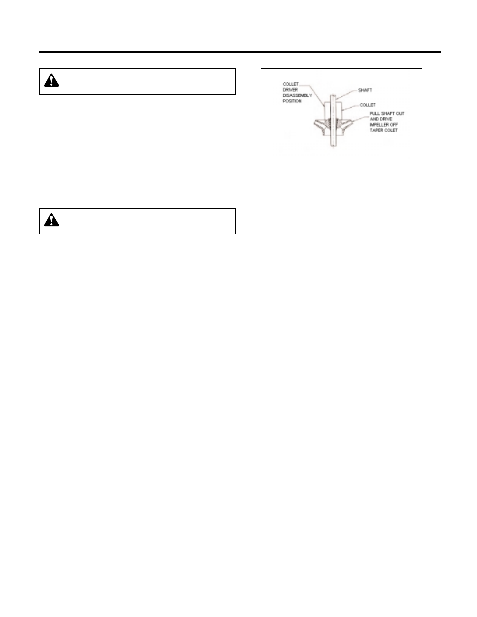
3. Pull shaft out as far as possible and strike impeller hub uti-
lizing a collet driver or equivalent sliding along the pump
shaft to drive the impeller off the taper collet (See Figure 9).
4. After the impeller is freed, insert a screwdriver into the slot
in the taper collet and spread it to remove the collet. Slide
the collet off the pump shaft.
5. Repeat the above procedures until the bowl assembly is
completely disassembled.
KEYED CONSTRUCTION BOWL DISASSEMBLY
(Fire Pump Option)
1. Remove capscrews that secure discharge bowl (669) to
intermediate bowl (670).
2. Slide discharge bowl off the pump shaft (660).
3. Remove capscrews (759) and split thrust ring (725) from
pump shaft.
4. Slide impeller off the pump shaft and remove the key (730).
If impeller is seized to the shaft, strike impeller with a fiber
mallet and drive impeller off the pump shaft.
5. Repeat the above procedures until the bowl assembly is
completely disassembled.
TURBINE BOWL – WEAR RING REMOVAL
1. Remove set screws or grind off tack weld, when rings are
furnished with those locking methods.
2. Utilizing a diamond point chisel, cut two "V" shaped
grooves on the bowl wear ring approximately 180º apart.
Use extreme care not to damage the wear ring seat.
3. With a chisel or drift, knock the end of one half of the ring
in, and pry the ring out.
4. On special materials such as chrome steel, set up the bowl
in a lathe and machine the wear ring off using extreme care
not to machine or damage the ring seat.
BOWL, SUCTION BELL AND
LINESHAFT BEARING REMOVAL
1. Utilizing an arbor press and a piece of pipe or sleeve with
an outside diameter slightly smaller than the diameter of
the bowl or lineshaft bearing housing bore, press the bear-
ing out.
2. Remove suction bell bearing by setting the suction bell in a
lathe and machine the bearing off. The suction bell bearing
can also be removed by using bearing pullers to pull the
bearing out.
NOTE
: Bowl bearings are press fit. Do not remove unless
replacement is necessary.
WARNING
: Never try to lift entire pump assembly by
the lifting lugs or eyebolts furnished for the driver only.
WARNING
: Before starting, lock out driver power to
prevent accidental startup and physical injury.
Figure 9