Xylem A-C Fire Pump – Vertical Turbine Fire Pump AC8499 User Manual
Page 15
15
5. Fit gib key (760) into keyway, by filing if necessary, to
where there is a snug but sliding fit. This key must be able
to be removed by gentle leverage with a screwdriver under it.
6. Be careful that the gib key (760) is not too high so as to
hold up the adjusting nut (604) from seating on the drive
coupling. If it is, cut off some of it.
7. Install adjusting nut (604) to hand tight.
GEAR DRIVES WITH ENGINES
1. The procedure for installing a hollow shaft gear is exactly
the same as for the motor.
2. Checking pump rotation is very simple matter. Check the
arrows of rotation on the engine. Throw out the clutch, take
a bar and jack over the flexible driveshaft in direction of
engine rotation, and note if it turns the pump shaft in the
proper direction. Note: engines almost invariably turn
clockwise when looking toward the gear drive.
COMBINATION ENGINE AND MOTOR DRIVES
1. On combination drivers, the motor is invariably on top with
a projecting head shaft extension.
2. Follow all procedures outlined on page 19, except that the
motor must be lowered over this extended driveshaft and
great care must be taken to center it exactly so as not to
bump or miss-align the shaft while the motor is being
lowered into place.
3. There are several methods of running engines without
electric motors and vise versa, requiring simple adjustment
to the combination drive, but they are too numerous to
mention here and can be obtained from the gear manufac-
turers instructions included with the shipment.
IMPELLER ADJUSTMENT FOR ALL
HOLLOW SHAFT DRIVES
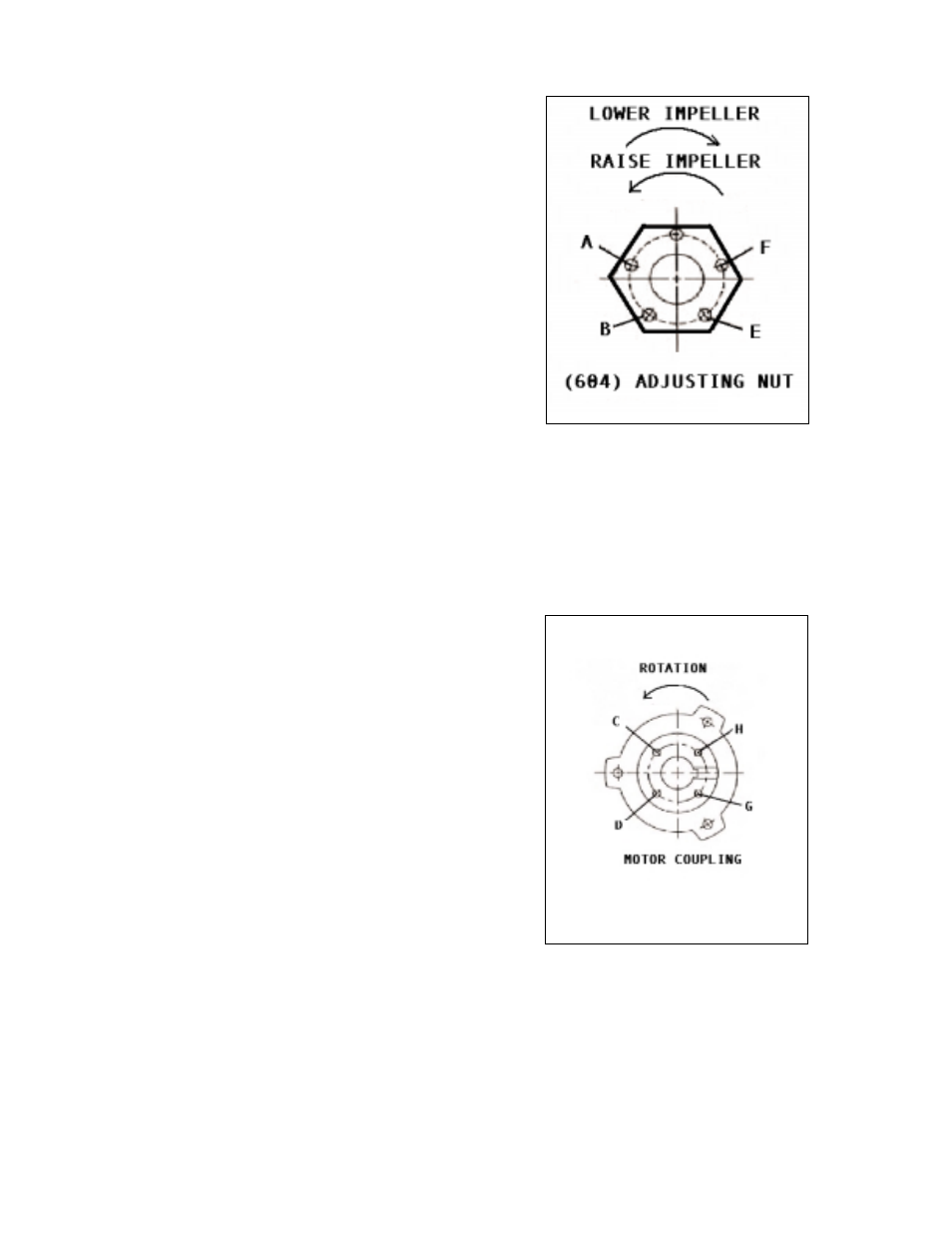
NOTE:
Shaft adjustment up or down is accomplished by turn-
ing the adjusting nut (604) Figure 7.
NOTE:
There are five holes in the adjusting nut and only four
in the motor coupling. See Figure 7 and Figure 8.
CLOSED IMPELLERS
1. The same procedure is followed as described under, "Gear
Drives with Engines", above. The adjustment is not critical.
A clearance of 1/8" to 3/16" (4.8mm) is considered
adequate. See Outline Drawing (if available) for this setting.
Figure 7
Figure 8