Application information – Diodes PAM8908 User Manual
Page 9
PAM8901 / PAM8908
Document number: DSxxxxx Rev. 1 - 1
9 of 12
www.diodes.com
December 2012
© Diodes Incorporated
PAM8901 / PAM8908
A Product Line of
Diodes Incorporated
Application Information
(cont.)
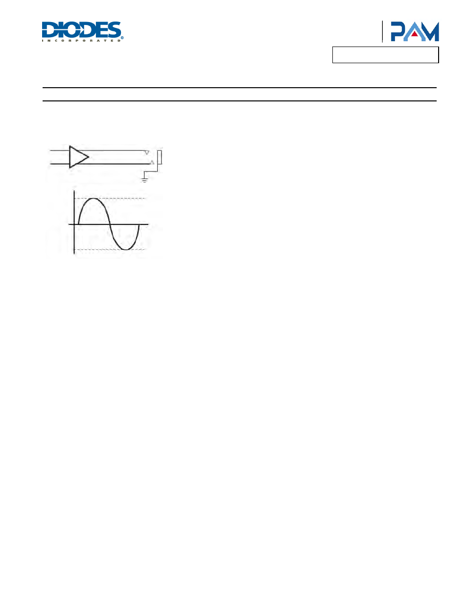
TrueCapFree Headphone Amplifiers
The TrueCapFree amplifier architecture operates from a single supply voltage and uses two internal charge pumps to generate a positive supply
and a rail for the headphone amplifier. The output voltages are centered around 0V and are capable of positive and negative voltage swings as
shown in the following drawing.
TrueCapFree amplifiers require no output DC-blocking capacitors. The headphone connector shield pin connects to ground and will interface
with headphones and non-headphone accessories. The PAM8901 / PAM8908 is a TrueCapFree amplifier.
LAYOUT RECOMMENDATIONS
Exposed Pad on PAM8901 / PAM8908
Solder the exposed metal pad on the PAM8901 / PAM8908 TQFN package to the landing pad on the PCB. Connect the landing pad to ground or
leave it electrically unconnected (floating). Do not connect the landing pad to PVDD or to any other power supply voltage.If the pad is grounded,
it must be connected to the same ground as the PGND. Soldering the thermal pad is required for mechanical reliability and enhances thermal
conductivity of the package.
GND Connections
The SGND pin is an input reference and must be connected to the headphone ground connector pin. This ensures no turn-on pop and minimizes
output offset voltage. Do not connect more than ±0.3V to SGND.
PGND is a power ground. Connect supply decoupling capacitors for PVDD, HPVDD, and HPVSS to PGND.
Power Supply Connections
Connect the supply voltage to the PVDD pin and decouple it with an X5R or better capacitor. Place both PVDD capacitor within 5mm of PVDD
pin on the PAM8901 / PAM8908. Ensure that the ground connection of PVDD capacitor has a minimum length return path to the device. Failure
to properly decouple the PAM8901 / PAM8908 may degrade audio or EMC performance.