Preliminary datasheet, Electrical characteristics (continued) – Diodes AZ4052 User Manual
Page 7
Preliminary Datasheet
Dual 4-channel Analog Multiplexer/Demultiplexer AZ4052
Oct. 2011 Rev. 1. 1 BCD Semiconductor Manufacturing Limited
7
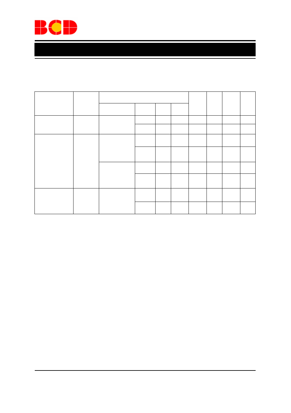
Electrical Characteristics (Continued)
Resistance R
ON
V
IS
is the input voltage at pins nYn or nZ, which is assigned as an input ((note 4) see figure 7)
Conditions
Parameter Symbol
Other
V
CC
(V)
V
EE
(V)
I
S
(
μA)
Min
Typ Max Unit
5.0 0
1000 73
180
Ω
On-resistance
(Peak)
R
ON
(Peak)
V
IS
=V
CC
to V
EE
,
V
I
=V
IH
or V
IL
10 0
1000 47
120
Ω
5.0 0
1000 55
130
Ω
V
IS
=V
EE
,
V
I
=V
IH
or V
IL
10 0
1000 40
100
Ω
5.0 0 1000
61 150
Ω
On-resistance
(Rail)
R
ON
(Rail)
V
IS
=V
CC
,
V
I
=V
IH
or V
IL
10 0 1000
45
110
Ω
5.0 0 5
Ω
Maximum
On-resistance
Difference
Between Any Two
Channels
R
ON
V
IS
=V
CC
to V
EE
,
V
I
=V
IH
or V
IL
10 0 6
Ω
Note 4: When supply voltages (V
CC
-V
EE
) near 2.0V the analog switch On-resistance becomes extremely
non-linear. When using a supply of 2V, it is recommended to use these devices only for transmitting digital
signals.