Apx803/d, Pin microprocessor reset circuit, Timing diagram – Diodes APX803/D User Manual
Page 7: Functional description
APX803/D
3-PIN MICROPROCESSOR RESET CIRCUIT
APX803
Document number: DS32132 Rev. 2 - 2
7 of 11
www.diodes.com
September 2010
© Diodes Incorporated
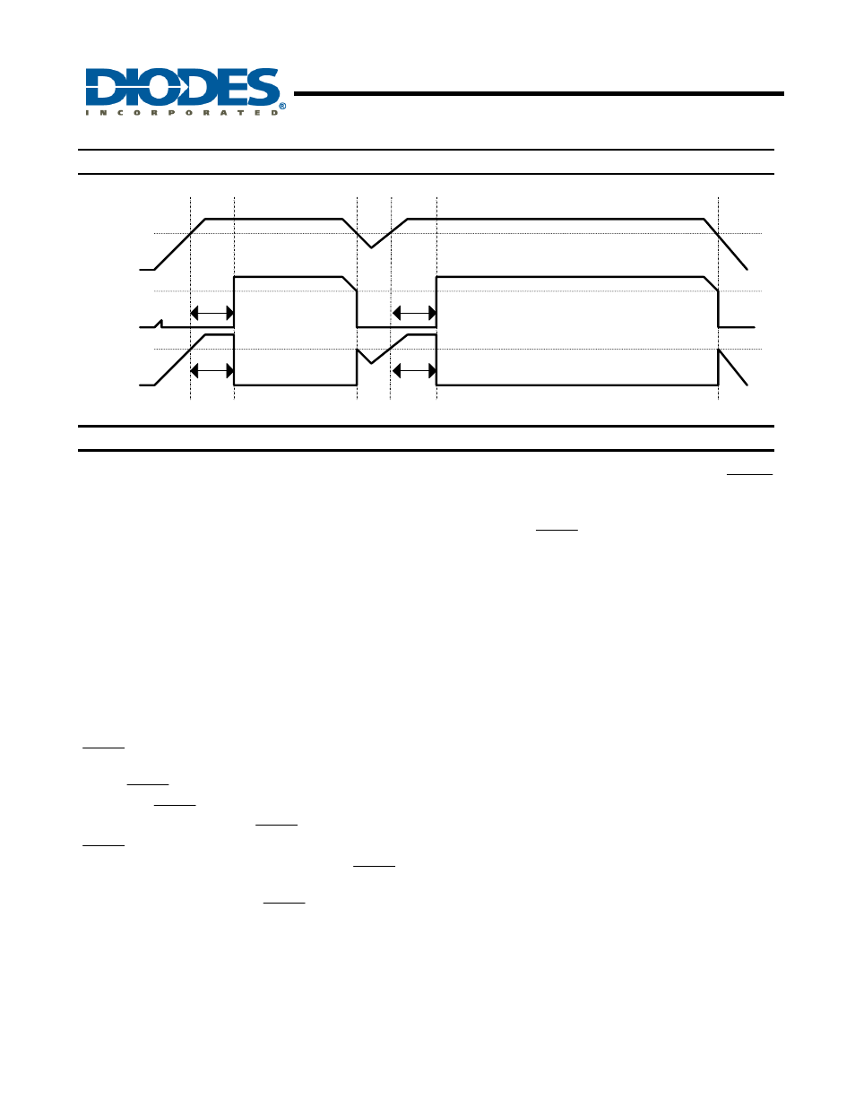
Timing Diagram
Vth
Vth
/RESET
RESET
T
Delay
T
Delay
T
Delay
T
Delay
Vcc
Vth
Functional Description
Microprocessors (µPs) and microcontrollers (µC) have a
reset input to ensure that it starts up in a known state.
The APX803/D drive the µP’s reset input to prevent
code-execution errors during power-up, power-down, or
brownout conditions. They assert a reset signal
whenever the V
CC
supply voltage declines below a
preset threshold and keep it asserted for a fixed period
of time after V
CC
has risen above the reset threshold. For
the APX803D this period is a minimum of 1ms while for
other APX803 variants it is at least 140ms. The
APX803/D have an open-drain output stage.
Ensuring a Valid Reset Output
Down to V
CC
= 0
RESET is guaranteed to be a logic low for V
CC
> 1V.
Once V
CC
exceeds the reset threshold, an internal timer
keeps RESET low for the reset timeout period; after
this interval, RESET goes high. If a brownout condition
occurs (V
CC
dips below the RESET reset threshold),
RESET goes low. Any time V
CC
goes below the reset
threshold, the internal timer resets to zero, and RESET
goes low. The internal timer starts after V
CC
returns
above the reset threshold, and RESET remains low for
the reset timeout period.
When V
CC
falls below 1V, the APX803/D
RESET
output no longer sinks current — it becomes an open
circuit. Therefore, high-impedance CMOS logic inputs
connected to RESET can drift to undetermined voltages.
This presents no problem in most applications since
most µP and other circuitry is inoperative with V
CC
below
1V.
Interfacing to µP with Bidirectional Reset Pins
Since the RESET output on the APX803/D is open drain,
this device interfaces easily with
μP/µC that have
bidirectional reset pins, such as the Motorola 68HC11.
Connecting the
μP supervisor’s RESET output directly to
the microcontroller’s (
μC’s) RESET pin with a single pull-
up resistor allows either device to assert reset.
Supervising and monitoring Multiple Supplies
Generally, the pull-up resistor connected to the
APX803/D will connect to the supply voltage that is being
monitored at the IC’s V
CC
pin. However, some systems
may use the APX803/D open-drain output to level-shift
from the monitored supply to reset the µP powered by a
different supply voltage or monitor multiple supplies that
will be fed into 1 µC/µP reset input.