Apx803/d, Pin microprocessor reset circuit, Electrical characteristics – Diodes APX803/D User Manual
Page 4
APX803/D
3-PIN MICROPROCESSOR RESET CIRCUIT
APX803
Document number: DS32132 Rev. 2 - 2
4 of 11
www.diodes.com
September 2010
© Diodes Incorporated
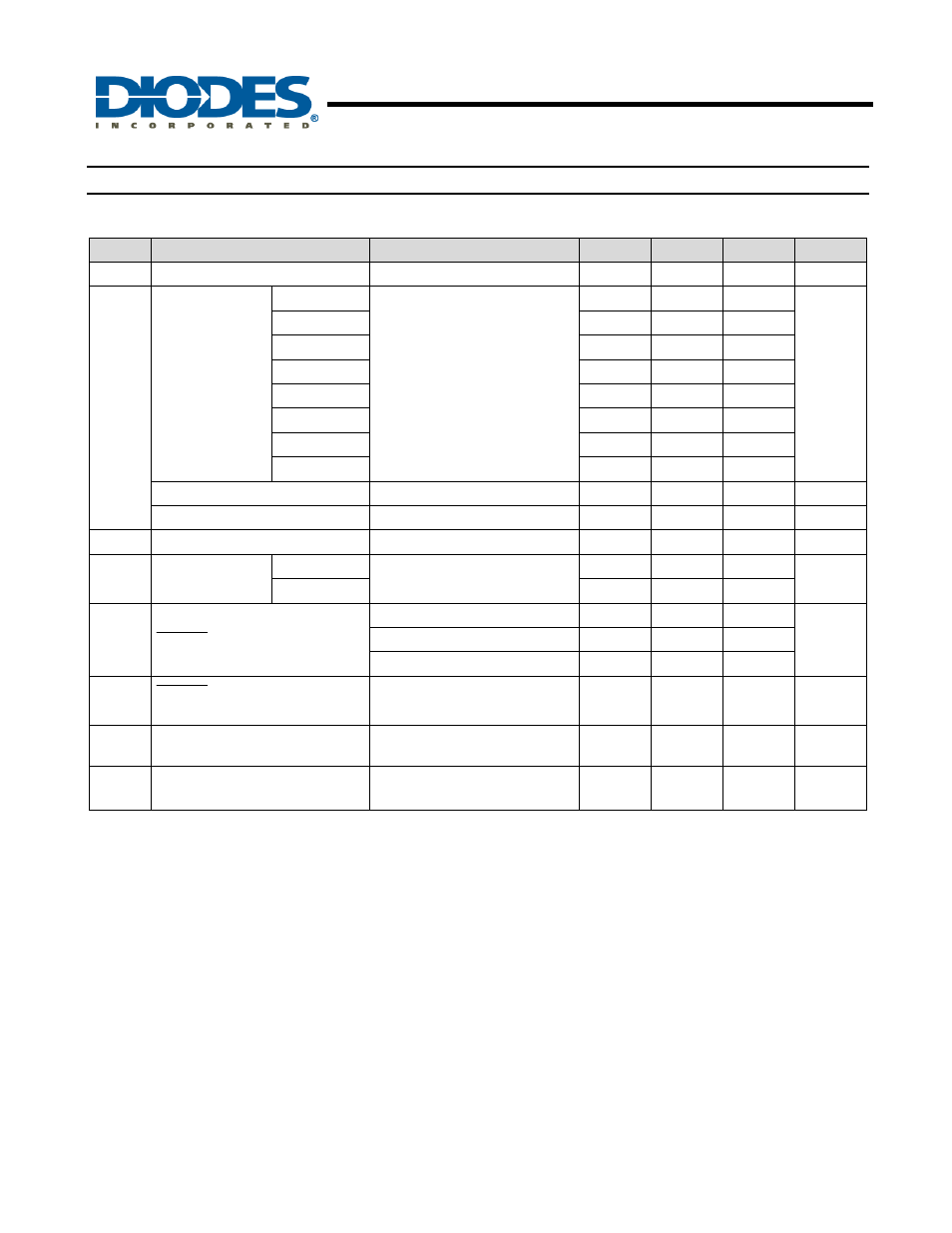
Electrical Characteristics
(T
A
= 25°C)
T
A
= -40 to 85
°
C unless otherwise note. Typical values are at T
A
=+25 °C.
Symbol
Parameter
Test Conditions
Min
Typ.
Max
Unit
I
CC
Supply
Current
V
TH
+ 0.2V
30
40
μA
V
TH
Reset Threshold
APX803-23
T
A
= 25
o
C
2.21 2.25 2.30
V
APX803-26
2.59 2.63 2.66
APX803-29
2.89 2.93 2.96
APX803D-29
2.89 2.93 2.96
APX803-31
3.04 3.08 3.13
APX803-40
3.94 4.00 4.06
APX803-44
4.31 4.38 4.45
APX803-46
4.56 4.63 4.70
Reset Threshold hysteresis
V
TH-H
– V
TH-L
40
mV
Reset Threshold Tempco
30
ppm/°C
t
S
V
CC
to RESET delay
V
CC
= V
TH
to (V
TH
– 100mV)
20
µs
t
DELAY
Reset Active
Timeout Period
APX803-XX
T
A
= 0
o
C to +85
o
C
140 200 280
ms
APX803D-29 1
3.3
V
OL
T
RESE
Output Voltage Low
V
CC
= V
TH
-0.2, I
SINK
= 1.2mA
0.3
V
V
CC
= V
TH
-0.2, I
SINK
= 3.5mA
0.4
V
CC
> 1.0V, I
SINK
= 50uA
0.3
I
OH
T
RESE
Output High leakage
current
V
CC
> V
TH
+0.2
1
µA
θ
JA
Thermal Resistance Junction-to-
Ambient
SOT23/SOT23R (Note 2)
201
°C/W
θ
JC
Thermal Resistance
Junction-to-Case
SOT23/SOT23R (Note 2)
56
°C/W
Notes:
2. Test condition for SOT23 and SOT23R: Devices mounted on FR-4 substrate PC board, 2oz copper, with minimum
recommended pad layout.
3. Final datasheet limits to be determined by characterization and correlation.