Block diagram, Absolute maximum ratings, Recommended operating conditions – Diodes AH183 User Manual
Page 3
AH182/AH183
LOW POWER HALL EFFECT SWITCH
AH182/AH183 Rev. 8
3 of 10
NOVEMBER 2009
DS31024
©
Diodes Incorporated
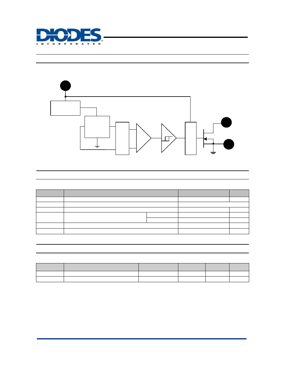
Block Diagram
1
Reg./Switch
Hall Plate
Amp
Output
3
Vdd
Gnd
2
O
ffs
e
t
C
anc
e
llin
g
Lo
gi
ca
l
Absolute Maximum Ratings
(T
A
= 25
°C)
Symbol
Parameter
Rating
Unit
Vdd Supply
Voltage
7
V
B Magnetic
Flux
Density
Unlimited
I
OUT
Output
current
10
mA
P
D
Power Dissipation
SIP-3L 550
mW
SC59
230 mW
T
J(MAX)
Maximum Junction Temperature
150
°C
T
ST
Storage Temperature Range
-65 to +150
°C
Recommended Operating Conditions
(T
A
= 25
°C)
Symbol
Parameter
Conditions
Min
Max
Unit
Vdd
Supply Voltage
Operating
2.5
5.5
V
T
A
Operating Ambient Temperature
Operating
-40
85
°C
This manual is related to the following products: