Diodes AH183 User Manual
Features general description, Applications typical circuit, Low power hall effect switch
AH182/AH183
LOW POWER HALL EFFECT SWITCH
AH182/AH183 Rev. 8
1 of 10
NOVEMBER 2009
DS31024
©
Diodes Incorporated
• Micropower
operation
•
2.5V to 5.5V battery operation
• Offset
Canceling
Technology
•
Superior temperature stability
• Extremely
Low
Switch-Point
Drift
•
Insensitive to Physical Stress
• -40°C to 85°C operating temperature
•
Lead Free packages: SIP-3L and SC59 (Commonly
known as SOT23 in Asia)
•
SIP-3L and SC59: Available in “Green” Molding
Compound (No Br, Sb)
•
Lead Free Finish / RoHS Compliant (Note 1)
AH182/AH183 is a three-terminal Hall effect sensor device with
an output driver, mainly designed for battery–operation,
hand-held equipment (such as cellular and cordless phones, and
PDA’s) The total operation power is down to 15uW in the
2.75V supply.
The south pole of sufficient strength will turn the output on in
SIP-3L but the north pole of sufficient strength will turn the output
on in SC59 package. The output will be turned off under no
magnetic field.
While the magnetic flux density (B) is larger than operation point
(Bop), the output will be turned on (low), the output is held until
B is lower than the release point (Brp), then turned off. The
difference between AH182 and AH183 is that the former
consumes less power than that of the latter in the Hall sensor
operation.
• Cover
detector
• Speed
measurement
• Home
safety
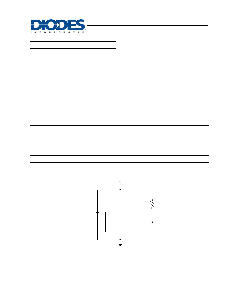
AH182/AH183
2.5~5.5V
Output
Gnd
R
L
C
*
C is for power stabilization and to strengthen the noise immunity, the recommended capacitance is 10nF~100nF.
R
L
is the pull-up resistor, the recommended resistance is 10Kohm~100Kohm.
Features
General Description
Applications
Typical Circuit *