Absolute maximum ratings, Recommended operating conditions, Electrical characteristics – Diodes AH2984 User Manual
Page 4: Ah2984
AH2984
Document number: DS31698 Rev. 4 - 2
4 of 10
December 2013
© Diodes Incorporated
AH2984
Absolute Maximum Ratings
(@T
A
= +25°C, unless otherwise specified.)
Symbol Conditions
Rating
Unit
V
DD
Supply Voltage
18
V
V
RDD
Reverse
V
DD
Polarity Voltage
-15 V
I
O(AVE)
Output Current
(Note 5)
500
mA
I
O(peak as hold)
800
P
D
Power Dissipation
SIP-4 550
mW
SOT89-5 800
mW
T
ST
Storage Temperature
-55 to +150
C
T
J
Maximum Junction Temperature
+150
C
θ
JA
Thermal Resistance (Note 6)
SIP-4 227
C/W
SOT89-5 168
C/W
θ
JC
Thermal Resistance (Note 6)
SIP-4 49
C/W
SOT89-5 36
C/W
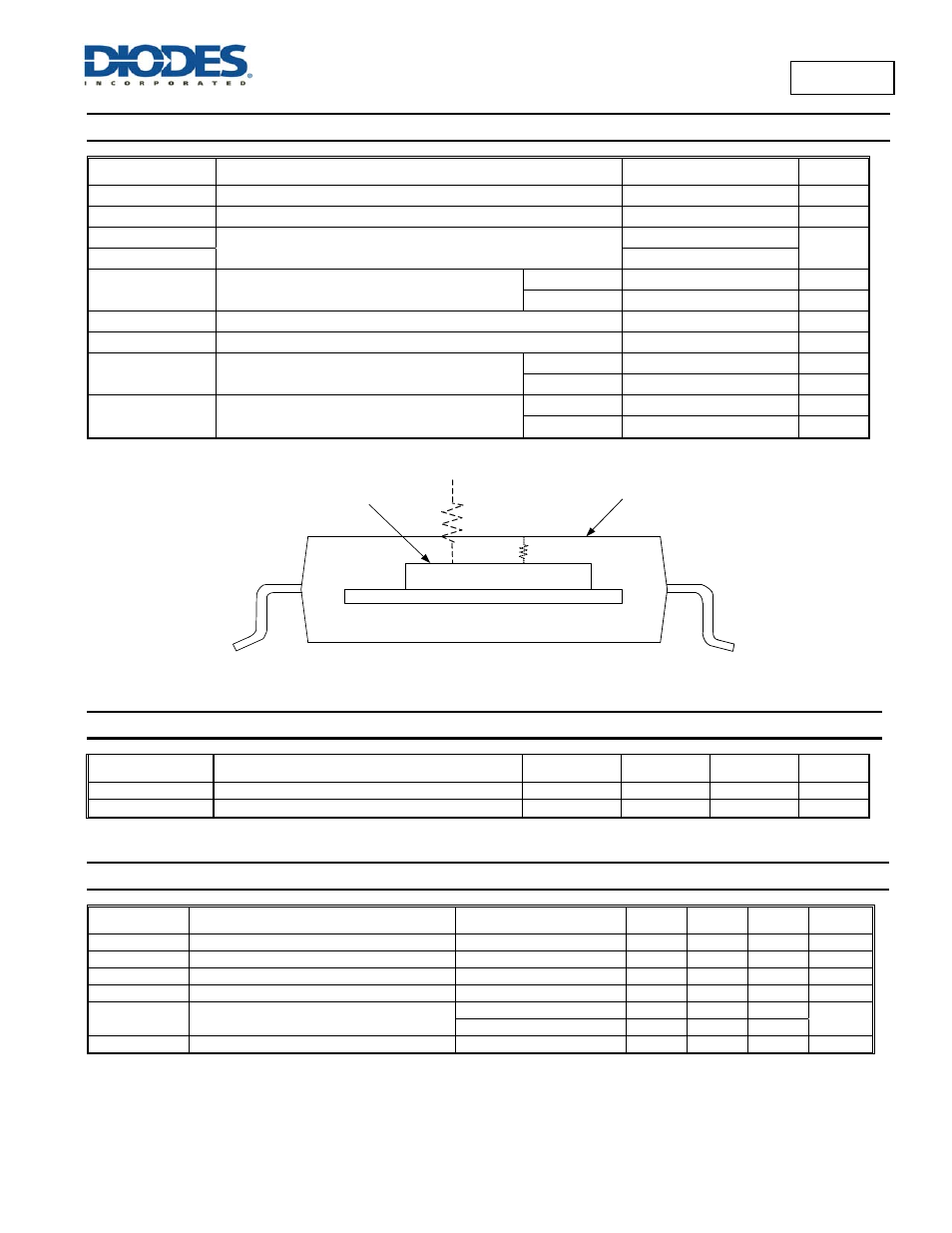
T
J
T
A
Tc
JC
JA
Recommended Operating Conditions
(@T
A
= +25°C, unless otherwise specified.)
Symbol Parameter
Conditions
Min
Max
Unit
V
DD
Supply Voltage
Operating
2.5
15
V
T
A
Operating Ambient Temperature (Note 5)
Operating
-40
+105
C
Electrical Characteristics
(@T
A
= +25°C; V
DD
= 12V; unless otherwise specified, Note 4)
Symbol Characteristics
Conditions
Min
Typ.
Max
Unit
I
DD
Supply Current
Operating, V
DD
= 12V
2.0 3.5 5.0 mA
T
on
Locked Protection On Time
—
—
0.25
—
s
T
off
Locked Protection Off Time
—
—
3.25
—
s
R
duty
Locked Protection Duty Ratio
T
off
/T
on
—
13
—
—
R
DS(ON)
Output On Resistance
I
O
= 300mA
—
1 1.67
Ω
I
O
= 500mA
—
1.25 1.8
V
Z
Output Zener-Breakdown Voltage
(Note 7)
24
33
42
V
Notes: 5. Shall not exceed P
D
and Safety Operation Area.
6. θ
JA
should be confirmed with heat sink thermal resistance. SOT89 exposed pad soldered to minimum recommended landing pads (see Package Outline
Dimension section) on 2”x2” two-layer 2oz.copper FR4 PCB with thermal vias in the exposed pad connecting to the copper flood on the bottom layer.
7.
The V
Z
value is in D.C voltage measurement. The V
Z
may vary with coils in A.C. voltage measurements.