Al8807a, Application information – Diodes AL8807A User Manual
Page 10
AL8807A
Document number: DS35990 Rev. 2 - 2
10 of 20
March 2013
© Diodes Incorporated
AL8807A
Application Information
AL8807A Operation
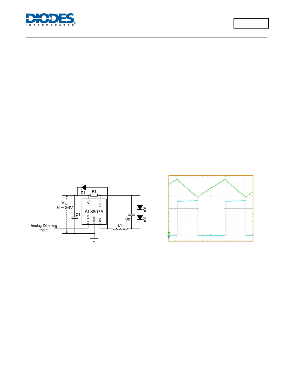
The AL8807A is a hysteretic LED current switching regulator sometimes known as an equal ripple switching regulator. In normal operation, when
voltage is applied at +V
IN
(See
Figure 31), the AL8807A internal switch is turned on. Current starts to flow through sense resistor R
1
, inductor L1,
and the LEDs. The current ramps up linearly, and the ramp rate is determined by the input voltage +V
IN
, and the inductor L1 (See Figure 32).
This rising current produces a voltage ramp across R
1
. The internal circuit of the AL8807A senses the voltage across R
1
and applies a
proportional voltage to the input of the internal comparator.
When this voltage reaches an internally set upper threshold, the internal switch is turned off. The inductor current continues to flow through R
1
,
L1, the LEDs and the schottky diode D1, and back to the supply rail, but it decays, with the rate of decay determined by the forward voltage drop
of the LEDs and the schottky diode.
This decaying current produces a falling voltage at R
1
, which is sensed by the AL8807A. A voltage proportional to the sense voltage across R
1
is
applied at the input of the internal comparator. When this voltage falls to the internally set lower threshold, the internal switch is turned on again.
This switch-on-and-off cycle continues to provide the average LED current set by the sense resistor R
1,
with a switching current determined by
the input voltage and LED chain voltage.
In normal operation the off time is relatively constant (determined mainly by the LED chain voltage) with only the on-time varying as the input
voltage changes. At duty cycles up to around 80% the ramp of the LED/switch current is very linear; however, as the duty cycle approaches 95%
the LED current ramp starts to become more exponential. This has two effects:
1.
The overall on time starts to increase lowering the overall switching frequency.
2.
The average LED current starts to increase – which may impact accuracy.
Figure 31 Typical Application Circuit
Figure 32 Typical Operating Waveform (C2 not fitted)
LED Current Control
With the CTRL pin open circuit, the LED current is determined by the resistor, R1, (see Figure 31), connected between V
IN
and SET. The
nominal average output current in the LED(s) is defined as:
1
R
V
I
TH
LED
where
V
TH
is nominally 100mV
For example for a desired LED current of 660mA the resulting resistor is:
m
150
66
.
0
1
.
0
I
V
1
R
LED
TH
V
IN
= 12V
T
A
=25ºC
2 LEDs
20ns/div
No C2
Ch2: 2V/div
Ch4: 100mA/div
Ch4: LED Current
Ch2: SW Pin