Ap3154a, Functional description, 120ma high efficiency white led driver – Diodes AP3154A User Manual
Page 9
AP3154A
120mA HIGH EFFICIENCY WHITE LED DRIVER
AP3154A Rev. 1
9
of
14
AUGUST 2009
©
Diodes Incorporated
Functional Description
General Functional Description
The AP3154A is designed for white LED applications. An
internal comparator circuit compares the voltage at each constant
current sink input against a reference voltage. To ensure
maximum power efficiency, the most appropriate switching mode
(x1, x1.5, x2) is automatically selected.
In applications, only four external components are required: two
1µF ceramic flying capacitors (C
1
and C
2
), one 1µF ceramic
capacitor each for input and output (C
IN
, C
OUT
).
AP3154A drives up to four white LEDs with a maximum current of
30mA each. A total of 120mA is provided to the four channels.
Through SDI, the current into each channel can be configured in
accordance to specific protocol and pre-defined values.
Maximum output current can be set to one of the four possible
scales: 2mA, 14mA, 20mA, 30mA. Among these, the ‘2mA’
setting is called “low current mode”. This would be useful for
applications which require very low operating current, e.g.
transmissive LCD panels.
For each maximum output current scale, there are 16 current
level settings separated from one another by approximately
1dB. While level-16 corresponds to maximum current output,
level-1 corresponds to zero output current. As the current level
varies logarithmically, intensity of the LED changes in a linear
fashion.
By default, all 4 channels are set to current level 1 (minimum
current level) after the chip is enabled or back from shutdown
mode.
The current level at the individual channels is configured via SDI
which supports data rate up to 10MHz. It allows the main
controller in the system to be offloaded to perform more
mission-critical functions.
Serial Digital Interface
SDI is a general purpose 1-wire digital interface designed to
transport digital controls for power management ICs such as
AP3154A. The current levels of the four channels can be
configured either together or individually. Up to 16 current
levels are allowed. A generic system controller can easily
support the SDI protocol via bit-banging over its general
purpose I/Os.
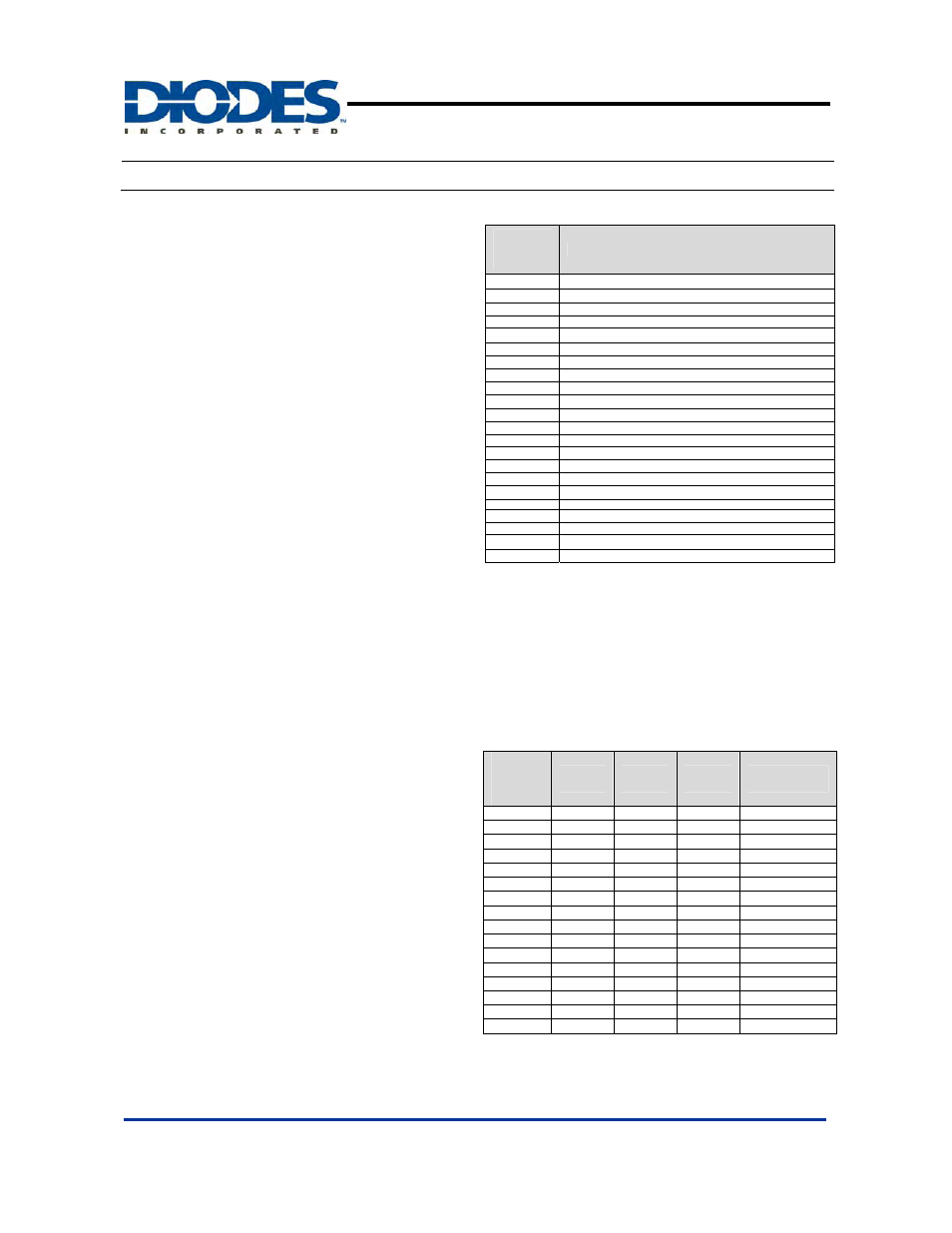
The SDI protocol is simple yet flexible enough to
accommodate different switching clock frequencies. Any
sequence of negative-edged pulses of 63 or less (see table 1),
separated by T
SEP
at the SDI pin is interpreted by AP3154A as
a channel configuration event. In the future, the number of
pulses can be extended to support additional commands.
In addition to the SDI protocol, dimming control can also be
achieved by presenting a timing-specific PWM signaling at the
SDI pin.
Number
of Falling
Edges
Command Description
1
Current level step up (1 up to level 16)
2
Current level step down (16 down to level 1)
3
Current level set to 16 (maximum current level)
4
Current level set to 1 (minimum current level)
5
All 4 Channels in dimming control
6
CH2, CH3 and CH4 in dimming control
7
CH1 and CH2 in dimming control
8
CH3 and CH4 in dimming control
9
CH1 in dimming control
10
CH2 in dimming control
11
CH3 in dimming control
12
CH4 in dimming control
13
Low-Current Mode (Maximum Current set to 2mA)
14
Maximum Current set to 14mA (All channels)
15
Maximum Current set to 20mA (All channels)
16
Maximum Current set to 30mA (All channels)
17
10% Up Spread Spectrum Control Enable/Disable
18
Switching Frequency set to 0.6Mhz
19
Switching Frequency set to 1.2Mhz
20
Switching Frequency set to 1.8Mhz
21~62 Reserved
63
PWM Dimming Control Enable/Disable
Dimming Control Current Level Setting
AP3154A supports four maximum output current scales including
30
mA, 20mA, 14mA, and 2mA low-current scales. For each
maximum current scale, there are 16 current level settings
separated from one another by appromimately 1dB (see table 2).
By default, maximum current scale is set to 20mA and dimming
control current level is set to maximum (level 16).
Through SDI, certain channels or all four channels can be
selected, and dimming control level for these channels can be set
to maximum (level 16), minimum (level1), up from minimum to
maximum or down from maximum to minimum (see table 1).
Dimming
Control
Current
Levels
I
out
(20mA)
I
out
(30mA)
I
out
(14mA)
Low-Current
(2mA)
16 20.0
30.0
14.0
2.0
15 17.8
26.7
12.5 1.78
14 15.9
23.8
11.1 1.59
13 14.3
21.4
10.0 1.43
12 12.7
19.0 8.9
1.27
11 11.1
16.7 7.8
1.11
10 10.2
15.2 7.1
1.02
9 8.9
13.3
6.2 0.89
8 7.9
11.9
5.6 0.79
7 7.0
10.5
4.9 0.70
6 6.3
9.5
4.4 0.63
5 5.7
8.6
4.0 0.57
4 5.1
7.6
3.5 0.51
3 4.4
6.7
3.1 0.44
2 4.1
6.2
2.9 0.41
1 0.05
0.05
0.05 0.05
Table 2: Dimming Control Current Level