Application information – Diodes AL8400 /AL8400Q User Manual
Page 7
AL8400/ AL8400Q
Document number: DS35115 Rev. 4 - 2
7 of 13
August 2012
© Diodes Incorporated
AL8400 /AL8400Q
Application Information
(cont.)
Bipolar Example – Choosing R
B
and C
L
The driver is required to control 3 series connected LEDs at 150mA ±10% from a 12V ±5% supply. Each LED has a forward voltage of 3V
minimum and of 3.6V maximum.
From this information the minimum supply voltage is 11.4V and the maximum LED chain voltage is 10.8V. Rearranging equation 1 (page 7); the
minimum voltage drop across the bipolar transistor is determined to be:
V
4
.
0
V
2
.
0
V
8
.
10
V
4
.
11
V
V
V
V
FB
max
LED
min
CC
CE
=
−
−
=
−
−
=
We will use the DNLS320E bipolar transistor (Q2.)
R
Bmax
The DNLS320E datasheet table states:
V
CE(SAT)max =
0.1V at I
C
= 100mA, I
B
= 0.5mA
h
FEmin
= 500 @ I
C
= 100mA, V
CE
= 2V;
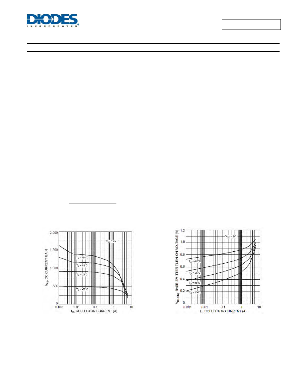
The datasheet graph (see left) shows a very slow variation at 100mA, so a value of 500 is considered appropriate.
Then
500
mA
150
I
max
B
=
= 0.3mA
The minimum recommended I
OUT
for AL8400 is 0.3mA and the maximum V
BE
, according to the DNLS320E datasheet graph (Figure 6), is
approximately 0.8V at -55°C.
From these and equation 3, the maximum allowed bias resistor value is:
=
+
−
−
=
max
B
min
OUT
FB
max
BE
min
CC
max
B
I
I
V
V
V
R
0003
.
0
0003
.
0
2
.
0
8
.
0
4
.
11
+
−
−
=
= 17.3k
Ω
Figure 5 DNLS320E H
FE
vs. I
C
Figure 6 DNLS320E V
BE
vs. I
C