Recommended operating conditions, Electrical characteristics, Typical characteristics – Diodes AL8400 /AL8400Q User Manual
Page 3
AL8400/ AL8400Q
Document number: DS35115 Rev. 4 - 2
3 of 13
August 2012
© Diodes Incorporated
AL8400 /AL8400Q
Recommended Operating Conditions
(@T
A
= +25°C, unless otherwise specified.)
Symbol Parameter Min
Max
Units
V
CC
Supply Voltage Range
2.2
18
V
V
OUT
OUT Voltage Range
0.2
18
I
OUT
OUT
Pin
Current
0.3 15 mA
T
A
Operating Ambient Temperature Range
-40
+125
°C
Electrical Characteristics
(Note 4) (@T
A
= +25°C, V
CC
= 12V, V
OUT
= V
FB
, I
OUT
= 1mA,
unless otherwise specified.)
Symbol Parameter
Conditions
Min
Typ
Max
Units
V
FB
Feedback Voltage
T
A
= +25°C
0.194
0.2
0.206
V
T
A
= -40°C to +125°C
0.190
0.210
FB
LOAD
Feedback Pin Load Regulation
I
OUT
= 1 to 15mA
T
A
= +25°C
3.1
6
mV
T
A
= -40°C to +125°C
10
FB
LINE
Feedback Pin Line Regulation
V
CC
= 2.2V to 18V
T
A
= +25°C
0.1
1.5
mV
T
A
= -40°C to +125°C
2
FB
OVR
Output Voltage Regulation
V
OUT
= 0.2V to 18V, I
OUT
=1mA
(Ref. Figure 1)
T
A
= +25°C
2
mV
T
A
= -40°C to +125°C
3
I
FB
FB Input Bias Current
V
CC
= 18V
T
A
= +25°C
-45
nA
T
A
= -40°C to +125°C
-200 0
I
CC
Supply
Current
V
CC
= 2.2V to 18V, I
OUT
=10mA
T
A
= +25°C
0.48
1
mA
T
A
= -40°C to +125°C
1.5
I
OUT(LK)
OUT
Leakage
Current
V
CC
= 18V, V
OUT
= 18V, V
FB
=0V
T
A
= +25°C
0.1
µA
T
A
= +125°C
1
Z
OUT
Dynamic
Output
Impedance
I
OUT
= 1 to 15mA, f < 1kHz
T
A
= +25°C
0.25
0.4
Ω
T
A
= -40°C to +125°C
0.6
PSRR
Power Supply Rejection Ratio
f = 300kHz, V
AC
= 0.3V
PP
T
A
= +25°C
45
dB
BW
Amplifier Unity Gain Frequency
T
A
= +25°C
600
kHz
G Amplifier
Transconductance
T
A
= +25°C
4500
mA/V
Note:
4. Production testing of the device is performed at +25°C. Functional operation of the device and parameters specified over the operating temperature
range are guaranteed by design, characterization and process control.
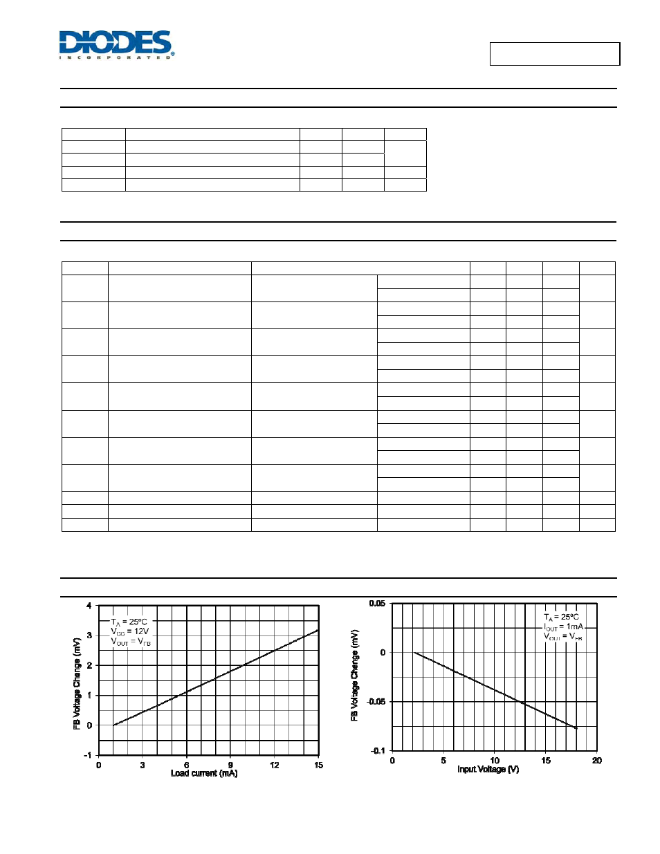
Typical Characteristics
Load Regulation
Line Regulation