New prod uc t al5812, Package thermal data, Recommended operating conditions – Diodes AL5812 User Manual
Page 3: Electrical characteristics
AL5812
Document number: DS35616 Rev. 2 - 2
3 of 11
November 2013
© Diodes Incorporated
NEW PROD
UC
T
AL5812
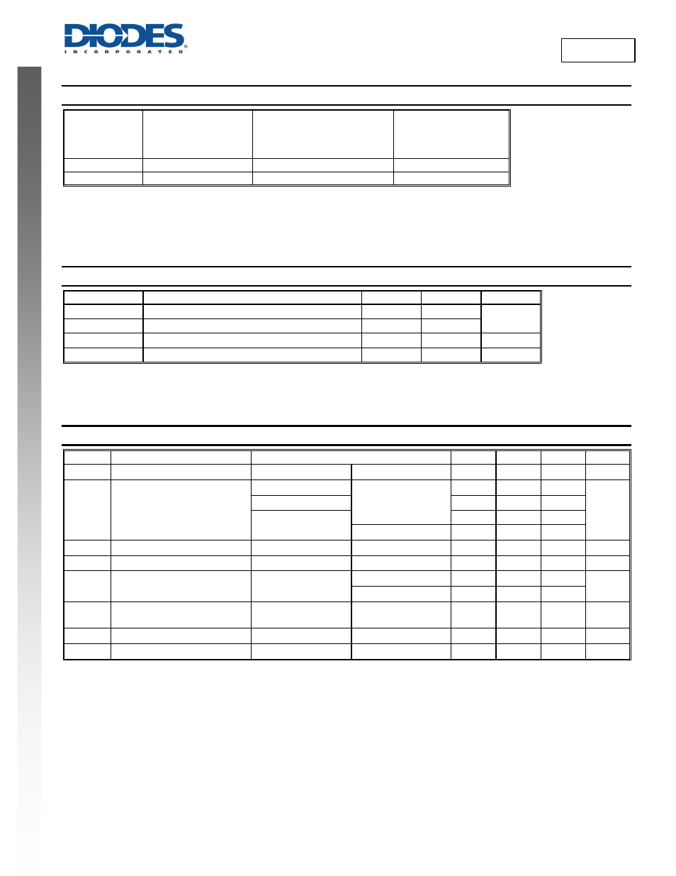
Package Thermal Data
Package
θ
JC
Thermal Resistance
Junction-to-Case
(Note 7)
θ
JA
Thermal Resistance
Junction-to-Ambient
(Note 7)
P
DIS
T
A
= +25°C, T
J
= +125°C
(Note 7)
MSOP-8EP
39
90°C/W (Note 5)
1.1W
U-DFN3030-6
14
69°C/W (Note 6)
1.47W
Notes:
5. Test condition for MSOP-8EP: Device mounted on FR-4 PCB (51mm x 51mm 2oz copper, minimum recommended pad layout on top layer and
thermal vias to bottom layer ground plane. For better thermal performance, larger copper pad for heat-sink is needed.
6. Test condition for U-DFN3030-6: Device mounted on FR-4 PCB (51mm x 51mm 2oz copper, minimum recommended pad layout on top layer and
thermal vias to bottom layer with maximum area ground plane. For better thermal performance, larger copper pad for heat-sink is needed
7. Dominant conduction path via exposed pad.
Recommended Operating Conditions
(@T
A
= +25°C, unless otherwise specified.)
Symbol Parameter Min
Max
Unit
V
CC
Supply Voltage Range Relative to GND Pin
3.5 60
V
V
LED
LED Pin Output Voltage Range Relative to GND Pin
1 60
I
LED
LED Pin Current (Notes 8 & 9)
10 150 mA
T
A
Operating Ambient Temperature Range
-40 +125 °C
Notes:
8. For improved accuracy LED current should be greater than 60mA.
9. Maximum LED current is also limited by ambient temperature and power dissipation such that junction temperature should be kept less than or equal
to +125°C.
Electrical Characteristics
(@T
A
= +25°C, V
CC
= 3.5V, V
LED
=1V (Note 10), R
SET
= 7.5kΩ
unless otherwise specified.)
Symbol Parameter
Conditions
Min
Typ
Max
Unit
V
RSET
R
SET
Voltage
T
A
= -40°C to +125°C
0.5 V
I
LED
I
LED
Current Accuracy
R
SET
= 12.5kΩ
T
A
= +25°C
57 60 63
mA
R
SET
= 4.99kΩ
142.5 150 157.5
R
SET
= 7.5kΩ
97 100 103
T
A
= -40°C to +125°C
95 105
REG
LINE
LED Current Line Regulation
V
CC
= 3.5V to 60V
T
A
= +25°C
0.25 %
UVLO Under
Voltage
Lockout
T
A
= -40°C to +125°C
2 V
I
CC
Supply Current
3.5V ≤ V
CC
≤ 60V
T
A
= +25°C
320
400
µA
T
A
= -40°C to +125°C
500
I
LEAK
LED Pin Leakage Current
V
CC
= V
LED
= 60V
R
SET
= Open Circuit
T
A
= +125°C
1
µA
T
SHDN
Thermal
Shutdown
155
°C
T
HYS
Thermal
Shutdown
Hysteresis
20
°C
Note:
10. All voltages unless otherwise stated are measured with respect to GND pin.