New prod uc t ap9060, Thermal resistance, Recommended operating conditions – Diodes AP9060 User Manual
Page 3: Electrical characteristics, Ap9060
AP9060
Document number: DS36001 Rev. 2 - 2
3 of 9
August 2012
© Diodes Incorporated
NEW PROD
UC
T
AP9060
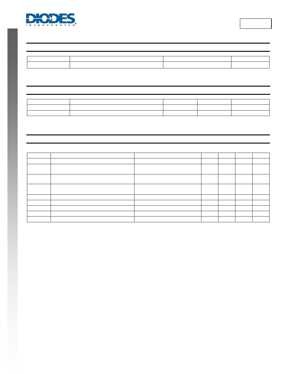
Thermal Resistance
(Note 6)
Symbol Parameter
Rating
Unit
θ
JA
Junction to Ambient
85
°C/W
Note:
6. Surface mounted on JEDEC’s High Effective Thermal Conductivity Test Board (JESD51-7).
Recommended Operating Conditions
(Note 7) (@T
A
= +25°C, unless otherwise specified.)
Symbol Parameter Min
Max
Unit
V
IN
Supply
Voltage
3
30
V
T
A
Operating Ambient Temperature Range
−40 +85 °C
Note:
7. The device function is not guaranteed outside of the recommended operating conditions.
Electrical Characteristics
(@T
A
= +25°C, unless otherwise specified.)
AP9060 is tested at V
IN
= 5V, I
OUT
= 0mA, unless otherwise noted.
Symbol Parameter
Test
Conditions
Min
Typ
Max
Unit
V
CLAMP
Output clamp voltage
V
IN
= 30V
10.8
11.15
11.5
V
R
ON
On-Resistance (Note 8)
V
IN
= 5V, I
OUT
= 1000mA
V
IN
= 3V, I
OUT
= 1000mA
90
105
120
139
m
Ω
V
pk
Peak Output Voltage (Note 9)
V
IN
goes from 0V to 30V with 100ns
rise time, C
OUT
= 100nF
16.0
V
I
bias
Input Bias Current
V
IN
= 5V
V
IN
= 30V
5
25
6
31
µA
THM
SD
Thermal Shutdown Threshold (Note 9)
R
OUT
= 10k
Ω
140
°C
THM
hyst
Thermal Shutdown Hysteresis(Note 9)
R
OUT
= 10k
Ω
20 °C
V
OUT_REV
Reverse Supply Voltage on VOUT(Note 10)
I
IN
=
−500mA
3.0
5.0
8.0
V
I
IN_REV
Reverse Load Current on VIN (Note 10)
V
OUT
= 5V
−500
−1000 mA
T
start
Soft-Start
Time
V
IN
= 5V
10
ms
Notes:
8. Pulse tested with a width of 20ms.
9. Guaranteed by design.
10. To support reverse power operation, as in the case of USB OTG systems. A voltage source is connected to V
OUT
and a load connected on V
IN
.