Ap6503, Application information – Diodes AP6503 User Manual
Page 12
AP6503
Document number: DS35077 Rev. 5 - 2
12 of 15
January 2013
© Diodes Incorporated
AP6503
Application Information
(cont.)
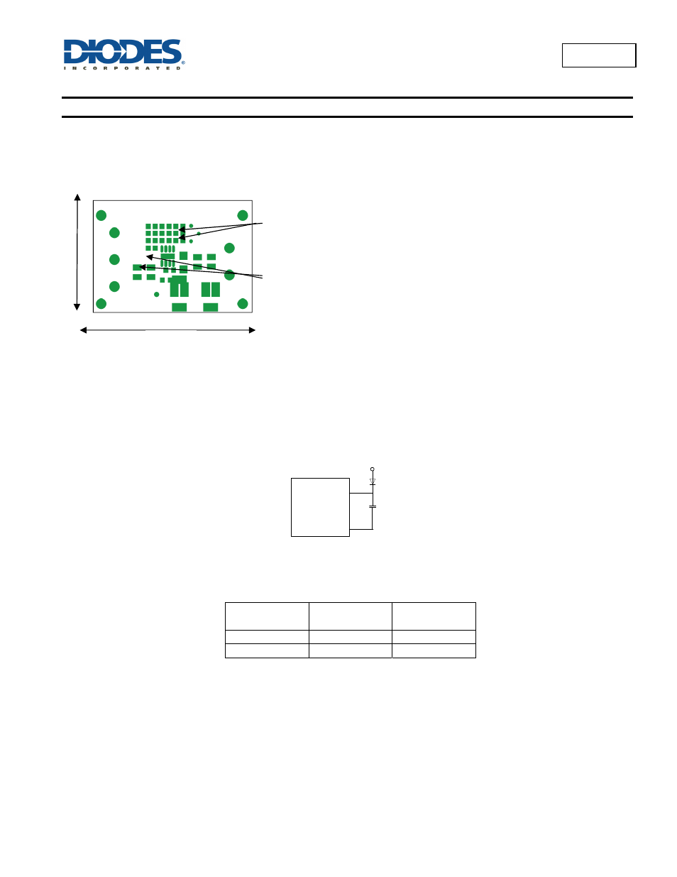
PC Board Layout
This is a high switching frequency converter. Hence attention must be paid to the switching currents interference in the layout. Switching current
from one power device to another can generate voltage transients across the impedances of the interconnecting bond wires and circuit traces.
These interconnecting impedances should be minimized by using wide, short printed circuit traces.
AP6503 is exposed at the bottom of the package and must be soldered directly to a well designed thermal pad on the PCB. This will help to
increase the power dissipation.
External Bootstrap Diode
It is recommended that an external bootstrap diode be added when the input voltage is no greater than 5V or the 5V rail is available in the
system. This helps to improve the efficiency of the regulator. This solution is also applicable for D > 65%. The bootstrap diode can be a low cost
one such as BAT54 or a schottky that has a low Vf.
AP6503
BST
SW
10nF
BOOST
DIODE
5V
4
3
Figure 7 – External Bootstrap
Compensation Components
Recommended Diodes:
Part Number
Voltage/Current
Rating
Vendor
B130
30V, 1A
Diodes Inc
SK13
30V, 1A
Diodes Inc
Input capacitor C1
must be placed as
close as possible
to the IC and to L1.
34mm
52mm
External feedback
resistor dividers
must be placed
close to the FB pin.