Ap5100, Applications information – Diodes AP5100 User Manual
Page 8
AP5100
1.2A STEP-DOWN CONVERTER with 1.4MHz SWITCHING
FREQUENCY
AP5100
Document number: DS32130 Rev. 3 - 2
8 of 12
April 2012
© Diodes Incorporated
Applications Information
(cont.)
Setting the Output Voltage
(cont.)
Choose the inductor ripple current to be 30% of the
maximum load current. The maximum inductor peak
current is calculated from:
2
L
ΔI
LOAD
I
L(MAX)
I
+
=
Equation 3
Peak current determines the required saturation current
rating, which influences the size of the inductor. Saturating
the inductor decreases the converter efficiency while
increasing the temperatures of the inductor, the MOSFET
and the diode. Hence choosing an inductor with
appropriate saturation current rating is important.
A 1µH to 10µH inductor with a DC current rating of at least
25% percent higher than the maximum load current is
recommended for most applications.
For highest efficiency, the inductor’s DC resistance should
be less than 200m
Ω. Use a larger inductance for
improved efficiency under light load conditions.
Input Capacitor
The input capacitor reduces the surge current drawn from
the input supply and the switching noise from the device.
The input capacitor has to sustain the ripple current
produced during the on time on the upper MOSFET. It
must hence have a low ESR to minimize the losses.
Due to large dI/dt through the input capacitors, electrolytic
or ceramics should be used. If a tantalum must be used, it
must be surge protected. Otherwise, capacitor failure
could occur. For most applications, a 4.7µF ceramic
capacitor is sufficient.
Output Capacitor
The output capacitor keeps the output voltage ripple small,
ensures feedback loop stability and reduces the overshoot
of the output voltage. The output capacitor is a basic
component for the fast response of the power supply. In
fact, during load transient, for the first few microseconds it
supplies the current to the load. The converter recognizes
the load transient and sets the duty cycle to maximum, but
the current slope is limited by the inductor value.
Maximum capacitance required can be calculated from the
following equation:
2
OUT
V
2
)
OUT
V
V
(
Δ
2
)
2
inductor
ΔI
OUT
L(I
o
C
−
+
+
=
Equation 4
Where
ΔV
is the maximum output voltage overshoot.
Where
inductor
ΔI
is the inductor ripple current.
ESR of the output capacitor dominates the output voltage
ripple. The amount of ripple can be calculated from the
equation below:
ESR
inductor
ΔI
capacitor
Vout
×
=
An output capacitor with ample capacitance and low ESR
is the best option. For most applications, a 22µF ceramic
capacitor will be sufficient.
External Diode
The external diode’s forward current must not exceed the
maximum output current. Since power dissipation is a
critical factor when choosing a diode, it can be calculated
from the equation below:
0.3V
out
I
)
IN
V
OUT
V
(1
diode
P
Ч
Ч
−
=
Equation 5
Note: 0.3V is the voltage drop across the schottky diode. A
diode that can withstand this power dissipation must be
chosen.
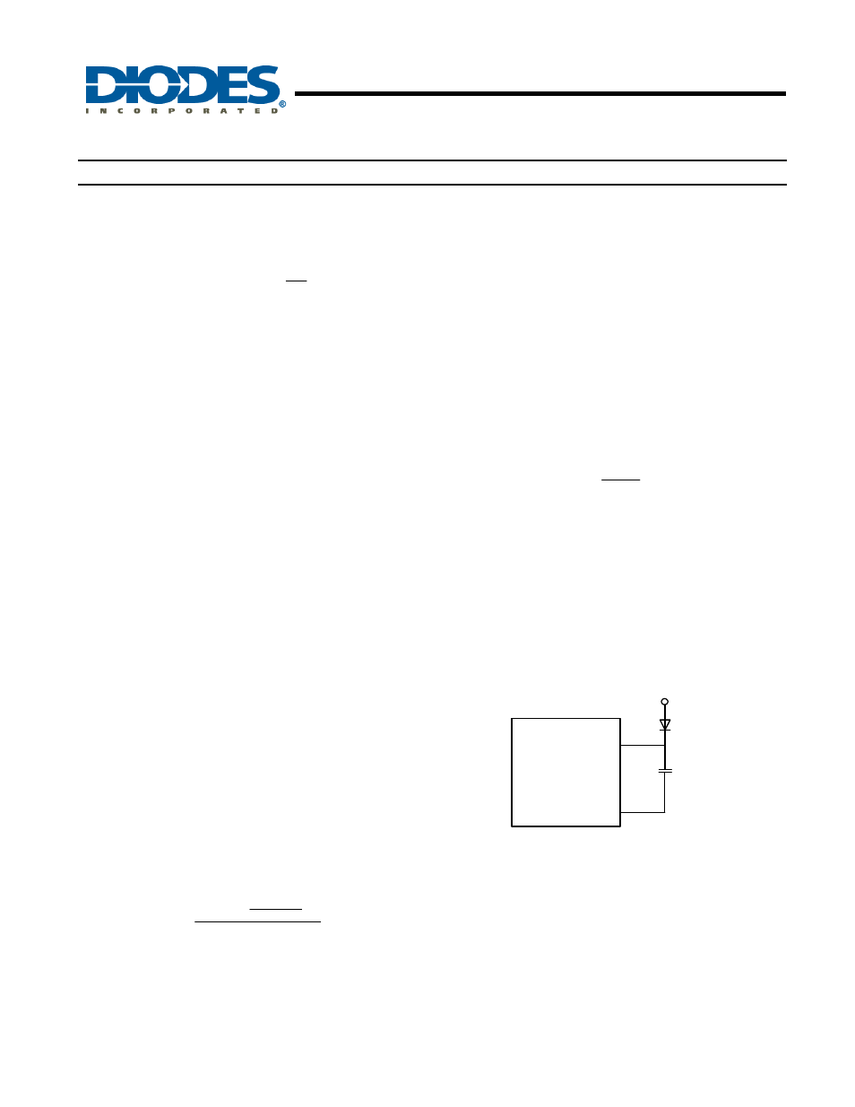
External Bootstrap Diode
It is recommended that an external bootstrap diode be
added when the input voltage is no greater than 5V or the
5V rail is available in the system. This helps improve the
efficiency of the regulator. The bootstrap diode can be a
low cost one such as IN4148 or BAT54.
AP5100
BST
SW
10nF
BOOST
DIODE
5V
1
6
Figure 6. External Bootstrap Diode
Under Voltage Lockout (UVLO)
Under Voltage Lockout is implemented to prevent the IC
malfunction from insufficient input voltages. For power-up,
the AP5100 must be enabled and the input voltage must
be higher than the UVLO rising threshold (4.0 V typ).
When the input voltage falls below the UVLO falling
threshold (UVLO rising threshold – UVLO hysteresis), the
AP5100 will latch an under voltage fault. In this event, the
output will fall low. To resume
normal operation, the
AP5100 must be pulled above the UVLO rising threshold.