Ap3591, Electrical characteristics – Diodes AP3591 User Manual
Page 6
AP3591
Document number: DS36906 Rev.
1 - 2
6 of 18
March 2014
© Diodes Incorporated
AP3591
N
E
W
P
R
O
D
U
C
T
A Product Line of
Diodes Incorporated
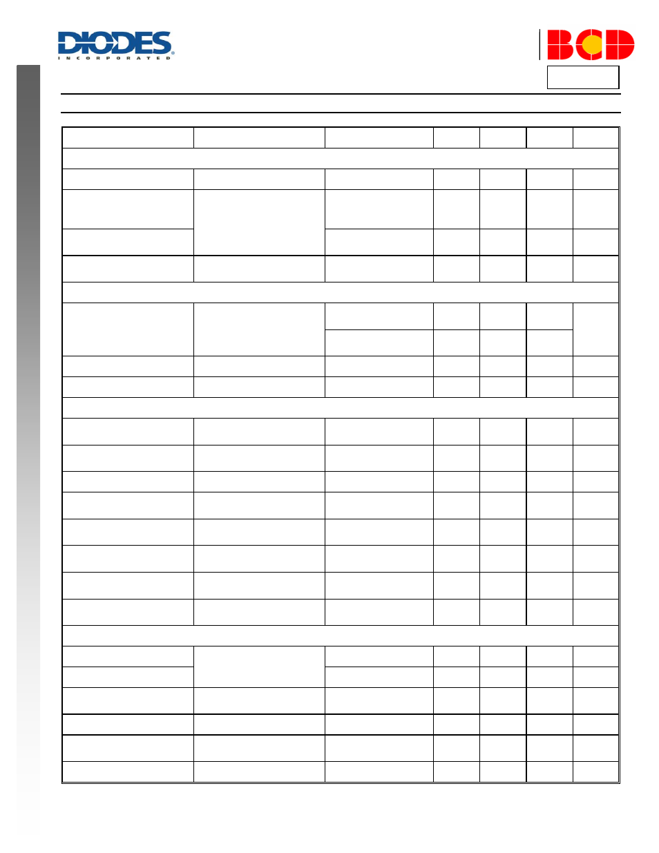
Electrical Characteristics
(V
IN
= 12V, V
DD
= V
DDP
= 5V, V
OUT
= 1.05V, T
A
= +25
o
C, unless otherwise specified.)
Symbol
Parameter
Conditions
Min
Typ
Max
Unit
SUPPLY INPUT
V
IN
Input Voltage
–
4.5
–
26
V
I
Q-CCM
Quiescent Current
VDD+VDDP current,
CCM, EN floating, V
FB
=
0.8V
–
500
800
µA
I
Q-DEM
V
DD
+V
DDP
current, DEM,
V
EN
= 5V, V
FB
= 0.8V
–
500
800
µA
I
SHDN
Shutdown Current
V
DD
+V
DDP
current, DEM,
V
EN
= 0V
–
1
10
µA
ON-TIME TIMER, OSCILLATOR FREQUENCY AND SOFT START
t
ON
On Time
V
PHASE
= 12V, V
OUT
=
2.5V, R
ON
=
200kΩ
510
630
750
ns
V
PHASE
= 12V, V
OUT
=
1.05V, R
ON
=
200kΩ
190
260
330
t
OFF-MIN
Min Off Time
–
250
400
580
ns
t
SS
Internal Soft Start Time
–
0.82
1.2
1.5
ms
PWM CONTROLLER GATE DRIVERS
R
U_PH
Upper Gate Pull-up Resistance
V
BOOT
-V
PHASE
= 5V,
50mA source current
–
3.3
7
Ω
R
U_GATE
Upper Gate Sink Resistance
V
BOOT
-V
PHASE
= 5V,
50mA sink current
–
1
3
Ω
R
L_PH
Lower Gate Pull-up Resistance
–
–
1.8
4
Ω
R
L_GATE
Lower Gate Sink Resistance
V
BOOT
-V
PHASE
= 5V,
50mA source current
–
0.5
2
Ω
–
PHASE Falling to LGATE
Rising Delay
V
PHASE
< 1.2V to
V
LGATE
> 1.2V
–
30
–
ns
–
LGATE Falling to UGATE
Rising Delay
V
LGATE
< 1.2V to
(V
UGATE
-V
PHASE
) > 1.2V
–
30
–
ns
V
BOOT
Boot Diode Forward Voltage
V
DDP
-V
BOOT
, I
BOOT
=
10mA
0.5
0.83
1
V
I
BSLK
V
BS
Leakage Current
V
BOOT
= 34V, V
PHASE
=
28V
–
0.1
1
µA
POWER GOOD
–
PGOOD Threshold
PGOOD from low to high
92.5
95
97.5
%
–
PGOOD from high to low
102
105
107
%
–
PGOOD Lower Threshold
Hysteresis
–
–
±5
–
%
V
PG_L
PGOOD Low Voltage
–
–
–
0.4
V
I
PG_LEAK
PGOOD Output Leakage
Current
V
PGOOD
= 5V
–
–
1
µA
t
DELAY
PGOOD Delay Time
Delay for PGOOD pin
16
22
36
µs