Operation description – Diodes AP3968/69/70 User Manual
Page 7
AP3968/69/70
Document number: DS36759 Rev. 2 - 2
7 of 15
December 2013
© Diodes Incorporated
AP3968/69/70
A Product Line of
Diodes Incorporated
Operation Description
+
C1
+
C
O
V
O
D1
R
FB1
R
FB2
R
CS
C
FB
CS
GND
AP3968/69/70
Ns
N
AUX
Np
Iout
Vs
V
AUX
v
IN
L
M
CPC
C
CPC
Q1
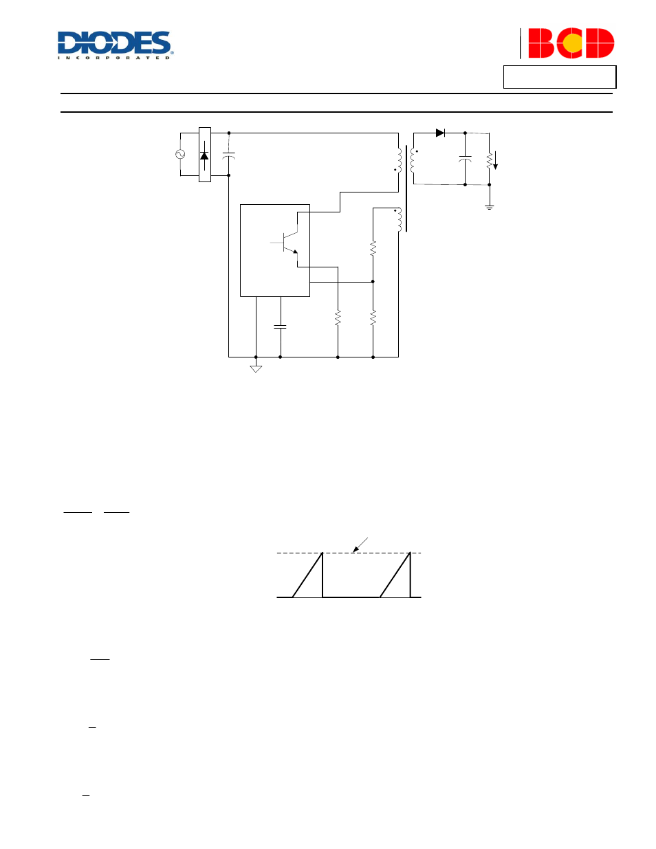
Figure 1. Simplified Flyback Converter Controlled by
AP3968/69/70
Figure 1 illustrates a simplified flyback converter controlled by AP3968/69/70.
Constant Primary Peak Current
The primary current Ip(t) is sensed by a current sense resistor R
CS
as shown in Figure 1.
The current rises up linearly at a rate of:
M
L
)
t
(
vg
dt
)
t
(
dip
………
…
(1)
Ip
0A
See equation 2
Figure 2. Primary Current Waveform
As illustrated in Figure 2, when the current Ip(t) rises up to Ipk, the switch Q1 turns off. The constant peak current is given by:
Rcs
Vcs
Ipk
…………(2)
The energy stored in the magnetizing inductance L
M
each cycle is therefore:
2
M
Ipk
L
2
1
Eg
…………(3)
So the power transferring from input to output is given by:
SW
2
M
f
Ipk
L
2
1
P
………
…(4)