Tlv431 – Diodes TLV431 User Manual
Page 9
TLV431
Document number: DS32088 Rev. 6 - 2
9 of 14
October 2012
© Diodes Incorporated
TLV431
A Product Line of
Diodes Incorporated
Application Notes
(cont.)
Printed Circuit Board Layout Considerations
The TLV431 in the SOT25 package has the die attached to pin 2, which results in an electrical contact between pin 2 and pin 5. Therefore, pin 2
of the SOT25 package must be left floating or connected to pin 5.
TLV431 in the SC70-6 (SOT363) package has the die attached to pin 2 and 5, which results in an electrical contact between pins 2, 5 and pin 6.
Therefore, pins 2 and 5 must be left floating or connected to pin 6.
Other Applications of the TLV431
R4
V
in
V
out
I
B
R1
R2
TLV431
GND
C1
0.1µF
ZXTP2039F
Q1
R3
I
SH
V
REF
⎟
⎠
⎞
⎜
⎝
⎛ +
=
2
R
1
R
1
V
V
REF
OUT
B
SH
OUT
IN
I
I
V
V
3
R
+
−
=
B
BE
I
V
4
R
=
mA
15
I
h
I
B
(min)
FE
SH
≤
<
⎟
⎟
⎠
⎞
⎜
⎜
⎝
⎛
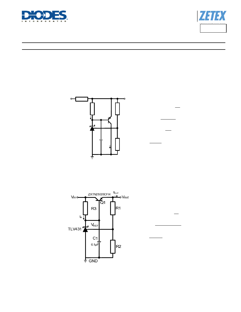
Figure 3. High Current Shunt Regulator
It may at times be required to shunt-regulate more current than the 15mA that the TLV431 is capable of.
Figure 3 shows how this can be done using transistor Q1 to amplify the TLV431’s current. Care needs to be taken that the power dissipation
and/or SOA requirements of the transistor is not exceeded.
⎟
⎠
⎞
⎜
⎝
⎛ +
=
2
R
1
R
1
V
V
REF
OUT
B
BE
OUT
IN
I
)
V
V
(
V
3
R
+
−
=
mA
15
I
h
I
B
(min)
FE
(max)
OUT
≤
<
⎟
⎟
⎠
⎞
⎜
⎜
⎝
⎛
Figure 4. Basic Series Regulator
A very effective and simple series regulator can be implemented as shown in Figure 4 above. This may be preferable if the load requires more
current than can be provided by the TLV431 alone and there is a need to conserve power when the load is not being powered. This circuit also
uses one component less than the shunt circuit shown in Figure 3 above.