Tlv431, Ordering information – Diodes TLV431 User Manual
Page 11
TLV431
Document number: DS32088 Rev. 6 - 2
11 of 14
October 2012
© Diodes Incorporated
TLV431
A Product Line of
Diodes Incorporated
Application Notes
(cont.)
Printed Circuit Board Layout Considerations (cont.)
V
in
V
out
V
R1
R2
TLV431
GND
C1
0.1µF
REF
VR1
Vin
Vout
GND
AP1117 or AP1084
1.2 V
R3
I
B
⎟
⎠
⎞
⎜
⎝
⎛ +
=
2
R
1
R
1
V
V
REF
OUT
)
V
V
(
V
REF
REG
OUT
+
≥
B
REG
OUT
IN
I
)
V
V
(
V
3
R
−
−
=
mA
18
I
mA
1
.
0
B
≤
≤
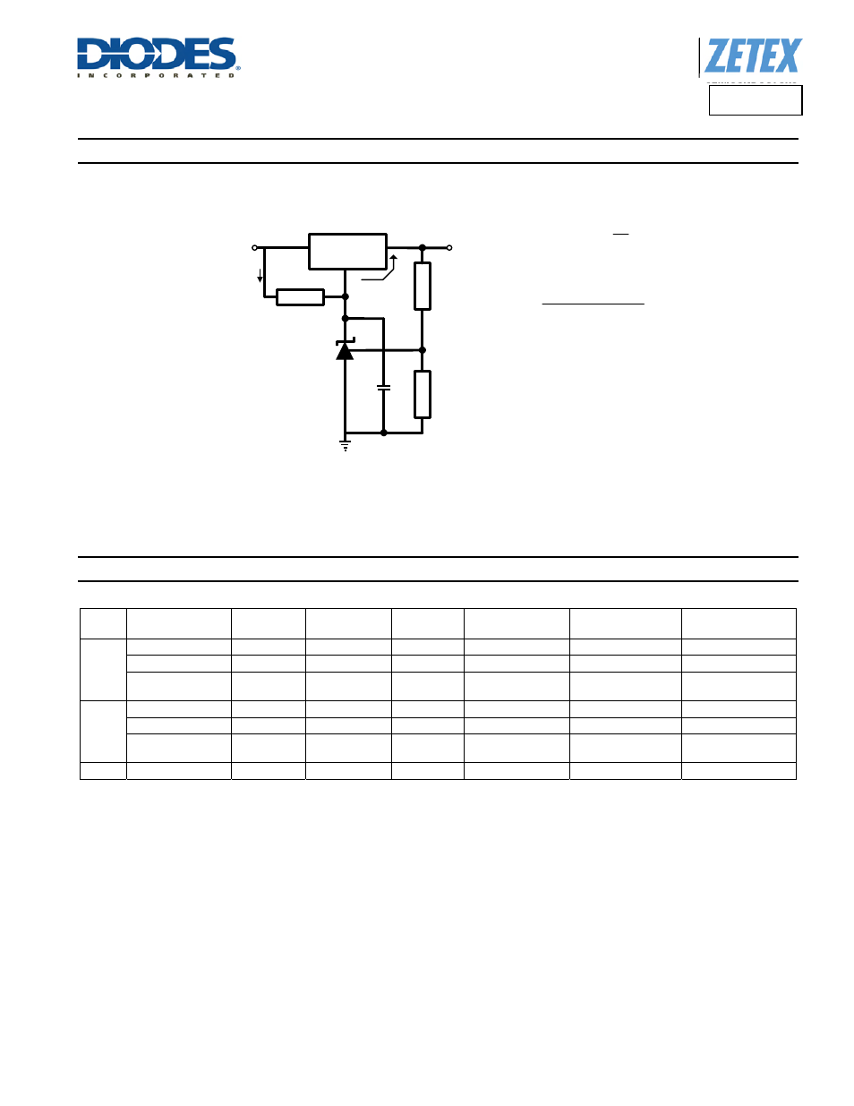
(All features of the regulator
such as short circuit
protection, thermal shutdown,
etc, are maintained.)
Figure 7. Adjustable Linear Voltage Regulator
Figure 7 is similar to Figure 6 with adjustability added. Note the addition of R3. This is only required for the AP1117 due to the fact that its ground
or adjustment pin can only supply a few micro-amps of current at best. R3 is therefore needed to provide sufficient bias current for the TLV431.
Ordering Information
Tol.
Part Number
Package
Part Mark
Status
Reel Size
Tape Width
Quanity per
Reel
1%
TLV431AE5TA
SOT25
V1A
Active
7”, 180mm
8mm
3000
TLV431AFTA
SOT23
V1A
Active
7”, 180mm
8mm
3000
TLV431AH6TA
SC70-6
(SOT363)
V1A
Active
7”, 180mm
12mm
1000
0.5%
TLV431BE5TA
SOT25
V1B
Active
7”, 180mm
8mm
3000
TLV431BFTA
SOT23
V1B
Active
7”, 180mm
8mm
3000
TLV431BH6TA
SC70-6
(SOT363)
V1B
Active
7”, 180mm
12mm
1000
0.2% TLV431TFTA
SOT23
V1T
Active
7”, 180mm
8mm
3000