Zxsc400 – Diodes ZXSC400 User Manual
Page 8
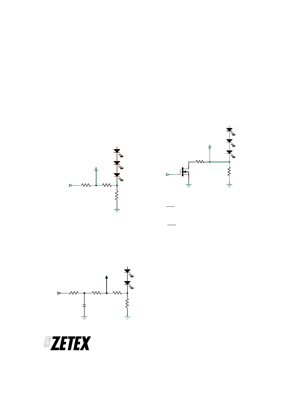
Dimming Control using a DC voltage
For applications where the shutdown pin is not
available a DC voltage can be used to control dimming.
By adding resistors R2 and R3 and applying a DC
voltage, the LED current can be adjusted from 100% to
0%. As the DC voltage increases, the voltage drop
across R2 increases and the voltage drop across R1
decreases, thus reducing the current through the LEDs.
Selection of R2 and R3 should ensure that the current
from the DC voltage is much less than the LED current
and much larger than the feedback current. The
component values in the diagram below represent 0%
to 100% dimming control from a 0 to 2V DC voltage.
Dimming Control using a filtered PWM signal
The filtered PWM signal can be considered as an
adjustable DC voltage by applying a RC filter. The
values shown in the diagram below are configured to
give 0% to 100% dimming for a 1kHz to 100kHz PWM
signal with a 2V amplitude. e.g. a 50% duty cycle will
give 50% dimming.
Dimming Control using a logic signal
For applications where the LED current needs to be
adjusted in discrete steps a logic signal can be applied
as shown in the diagram below. When Q1 os ‘off’, R1
sets the minimum LED current. When Q1 is ‘on’, R2 sets
the LED current that will be added to the minimum LED
current. The formula for selecting values for R1 and R2
are given below:
MOSFET ‘off’
I
V
R
LED(MIN)
FB
LEB
=
MOSFET ‘on’
I
V
R
I
LED(MAX)
FLB
LEB
LED(MIN)
=
+
Where V
FB
= 300mV
ZXSC400
ISSUE 1 - JANUARY 2003
8
R3
67k
R2
10k
R1
ZXSC400 V
FB
V
DC
R3
67k
R2
10k
R1
ZXSC400
PWM
R4
10k
C1
0.1µF
V
FB
R2
R1
ZXSC400 V
FB
LOGIC
SIGNAL
Q1