Zxsc400 – Diodes ZXSC400 User Manual
Page 6
Peak current definition
In general, the I
PK
value must be chosen to ensure that
the switching transistor, Q1, is in full saturation with
maximum output power conditions, assuming
worse-case input voltage and transistor gain under all
operating temperature extremes.
Once I
PK
is decided the value of R
SENSE
can be
determined by:
R
V
I
SENSE
SENSE
PK
=
Sense Resistor
A low value sense resistor is required to set the peak
current. Power in this resistor is negligible due to the
low sense voltage threshold, V
ISENSE
. At the bottom of
the page there is a table of recommended sense
resistors.
Output power calculation
By making the above assumptions for inductance and
peak current the output power can be determined by:
P
OUT
= I
AV
x V
IN
x
(Watts)
where
I
I
2
(T
T
)
(T
T
)
AV
PK
ON
DIS
ON
OFF
=
×
+
+
and
T
I
L
V
ON
PK
IN
=
×
and
T
I
L
(V
V )
DIS
PK
LED
IN
=
×
−
and
T
OFF
≅
1.7
s (internally set by ZXSC400)
and
= efficiency e.g. 100% = 1
Operating frequency can be derived by:
F
1
T
T
ON
OFF
=
+
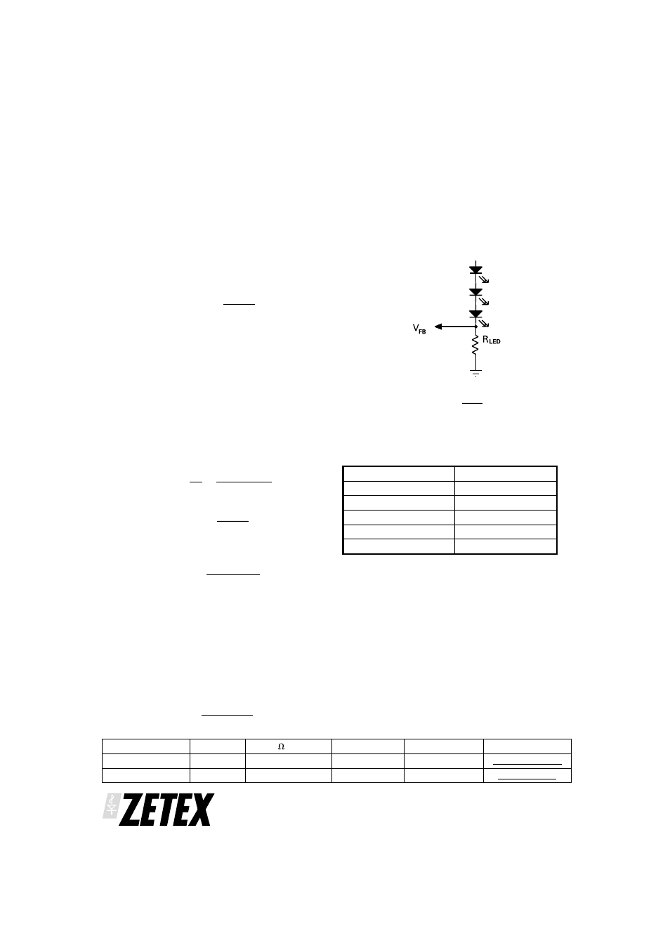
Programming LED current
Once the required output power is determined, the LED
current can be programmed by adding a single resistor
in the LED chain. The resistor value is determined by
the following:
I
V
R
LED
FB
LED
=
Where V
FB
= 300mV
RLED selection table
Shutdown Control
The ZXSC400 offers a shutdown mode that consumes
a standby current of less than 5
A. When the voltage at
the S
TDN
pin between 1V and 8V (and also open circuit),
the ZXSC400 is enabled and the driver is in normal
operation. When the voltage at the STDN pin is 0.7V or
lower, the ZXSC400 is disabled and the driver is in
shutdown mode. The SHDN input is a high impedance
current source of 1
A typ. The driving device can be an
open collector or an open drain or a logic output with a
“High“ voltage of 5V max. The device shutdown
current depends of the supply voltage, see typical
characteristics graph
ZXSC400
ISSUE 1 - JANUARY 2003
6
Manufacture
Series
R
DC
( ) Range
Size
Tolerance
URL
Cyntec
RL1220
0.022 - 10
0805
±5%
IRC
LR1206
0.010 - 1.0
1206
±5%
I
LED
R
LED
40mA
7.5
⍀
30mA
10
⍀
20mA
15
⍀
15mA
20
⍀
10mA
30
⍀