Pwm r4 10k, Application information – Diodes ZXSC410/ZXSC420/ZXSC440 User Manual
Page 9
ZXSC410/ZXSC420/ZXSC440
Document number: DS33618 Rev. 5 - 2
9 of 17
March 2013
© Diodes Incorporated
ZXSC410/ZXSC420/ZXSC440
Application Information
(cont.)
Dimming Control
There are many types of dimming control that can be implemented for the ZXSC410/420/440.
Dimming Control Using the Shutdown Pin
The first method uses the shutdown pin (only ZXSC410 and
ZXSC440). By injecting a PWM waveform on this pin and varying the
duty cycle, LED current and hence LED brightness can be adjusted.
To implement this method of brightness control on the ZXSC410/440,
a PWM signal with amplitude of between 0.7V and V
CC
at a
frequency of 120Hz or above (to eliminate LED flicker) should be
applied to the STDN pin. The LED current and hence LED brightness
is linearly proportional to the duty cycle ratio, so for brightness control
adjust duty cycle ratio as necessary. For example, a 10% duty cycle
equates to 10% of full LED brightness.
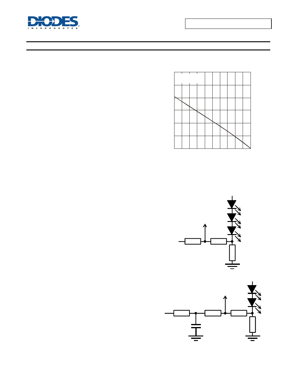
30
0
10
O
U
T
P
U
T
C
U
R
R
E
N
T
(A
)
20
40
20
0
100
80
60
DUTY CYCLE (%)
LED Current vs. Duty Cycle
4 White LEDs
V = V
= 3.3V
IN
EN
Dimming Control Using a DC Voltage
For applications where a PWM signal is not available or for the ZXSC420 a DC voltage can be used to control dimming by modulating the V
FB
pin.
By adding resistors R2 and R3 and applying a DC voltage, the LED
current can be adjusted from 100% to 0%. As the DC voltage
increases, the voltage drop across R2 increases and the voltage drop
across R1 decreases, thus reducing the current through the LEDs.
Selection of R2 and R3 should ensure that the current from the DC
voltage is much less than the LED current and much larger than the
feedback current. The component values in the diagram above
represent 0% to 100% dimming control from a 0 to 2V DC voltage.
R2
10k
R3
67k
R1
V
FB
V
DC
Dimming Control Using a Filtered PWM Signal
The filtered PWM signal can be considered as an adjustable
DC voltage by applying a RC filter (R4 and C1). The values
shown in the diagram below are configured to give 0% to
100% dimming for a 1kHz to 100kHz PWM signal with a 2V
amplitude. e.g. a 50% duty cycle will give 50% dimming.
C1
0.1µF
R2
10k
R3
67k
R1
V
FB
PWM
R4
10k