6 maintenance, Standby, Sensor replacement – Analytical Industries GPR-1200 MS ATEX Portable PPB Oxygen Analyzer User Manual
Page 24
24
An LED indicator located on the front panel will light continuously during the CHARGE cycle. A second LED indicator
located on the front panel provides a blinking 72 hour warning LOW BATT of the need to recharge the battery.
Caution: Operating the analyzer beyond this 72 hour warning may permanently damage the battery.
Standby
The analyzer has no special storage requirements. The sensor should remain connected during storage periods.
Store the analyzer with the power OFF. If storing for an extended period of time, charge before operating.
6 Maintenance
Generally, cleaning the electrical contacts or replacing filter elements is the extent of the maintenance
requirements of this analyzer.
Sensor Replacement
Periodically, the oxygen sensor will require replacement. The operating life is determined by a number of factors
that are influenced by the user and therefore difficult to predict. The Features & Specifications define the normal
operating conditions and expected life of the standard sensor utilized by the GPR-1200 MS Series analyzer.
Expected sensor life is inversely proportional to changes in oxygen concentration, pressure and temperature.
Serviceability: Except for replacing the oxygen sensor, there are no parts inside the analyzer for the operator to
service. Only trained personnel with the authorization of their supervisor should conduct maintenance.
Caution: DO NOT open the oxygen sensor. The sensor contains a corrosive liquid electrolyte that could be harmful
if touched or ingested, refer to the Material Safety Data Sheet contained in the Owner’s Manual. Avoid contact with
any liquid or crystal type powder in or around the sensor or sensor housing, as either
could be a form of electrolyte. Leaking sensors should be disposed of in accordance
with local regulations.
Procedure:
1. Remove the four (4) screws securing the analyzer’s front panel.
2. Caution: Do not discard the gaskets from the enclosure.
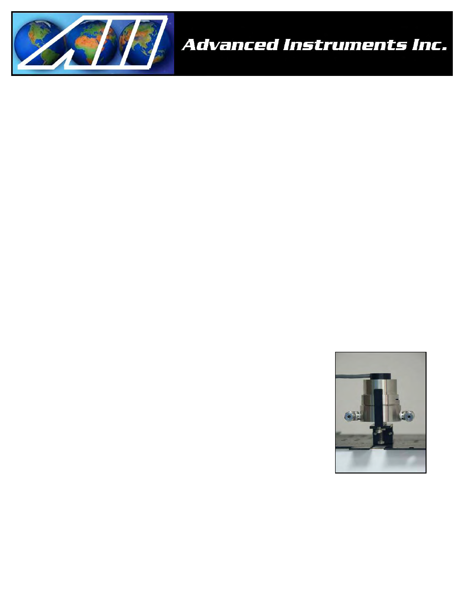
3. Using the 5/16 wrench supplied loosen but do not remove the clamp bolt located
in the center of the housing with the elbows attached.
4. Rotate the upper section of the sensor housing 90º to disengage from the clamp.
5. Remove the upper section by pulling it straight up and place it on a smooth
surface.
6. Remove the old oxygen sensor and dispose of it as you would a battery.
7. Remove the new oxygen sensor from the shipping bag.
8. Remove the red label and the gold ribbon (shorting device) from the PCB at the rear of the sensor.
9. Caution: Minimize the time the sensor is exposed to ambient air.
10. Place the new sensor in the bottom section of the sensor housing with the PCB facing up.
11. Place the upper section of the sensor housing over the sensor.
12. Gently push the upper section downward and rotate 90º to engage the clamp.
13. Finger tighten the clamp bolt and one full turn with the 5/16 wrench to compressed the o-ring seal.
14. Connect zero gas or low oxygen content sample gas line to purge the sensor of oxygen.
15. Make the SHUT OFF valve is open and the 3-way valve is in the SAMPLE position.
16. Calibrate the analyzer in approximately 1 hour, once the reading stabilizes.