Analytical Industries GPR-1200 MS ATEX Portable PPB Oxygen Analyzer User Manual
Page 22
22
The sensor is exposed to sample gas that must flow or be drawn through the analyzer’s internal sample system.
The sample system may include optional additional components such as a 3-way sample/span valve, a pressure
regulator, coiled metal tubing (samples must be cooled to at least 35-40º C for continuous use), coalescing filters,
scrubbers, 3-way sample/return valve, backpressure regulator, etc.
Note: The standard sample system is designed for positive pressure applications as described below under the
Installation section. From the factory the sensor is isolated inside the analyzer, sample system in the BYPASS
position, and the FLOW control valve set approx at 1 lpm (.5-1 SCFH).
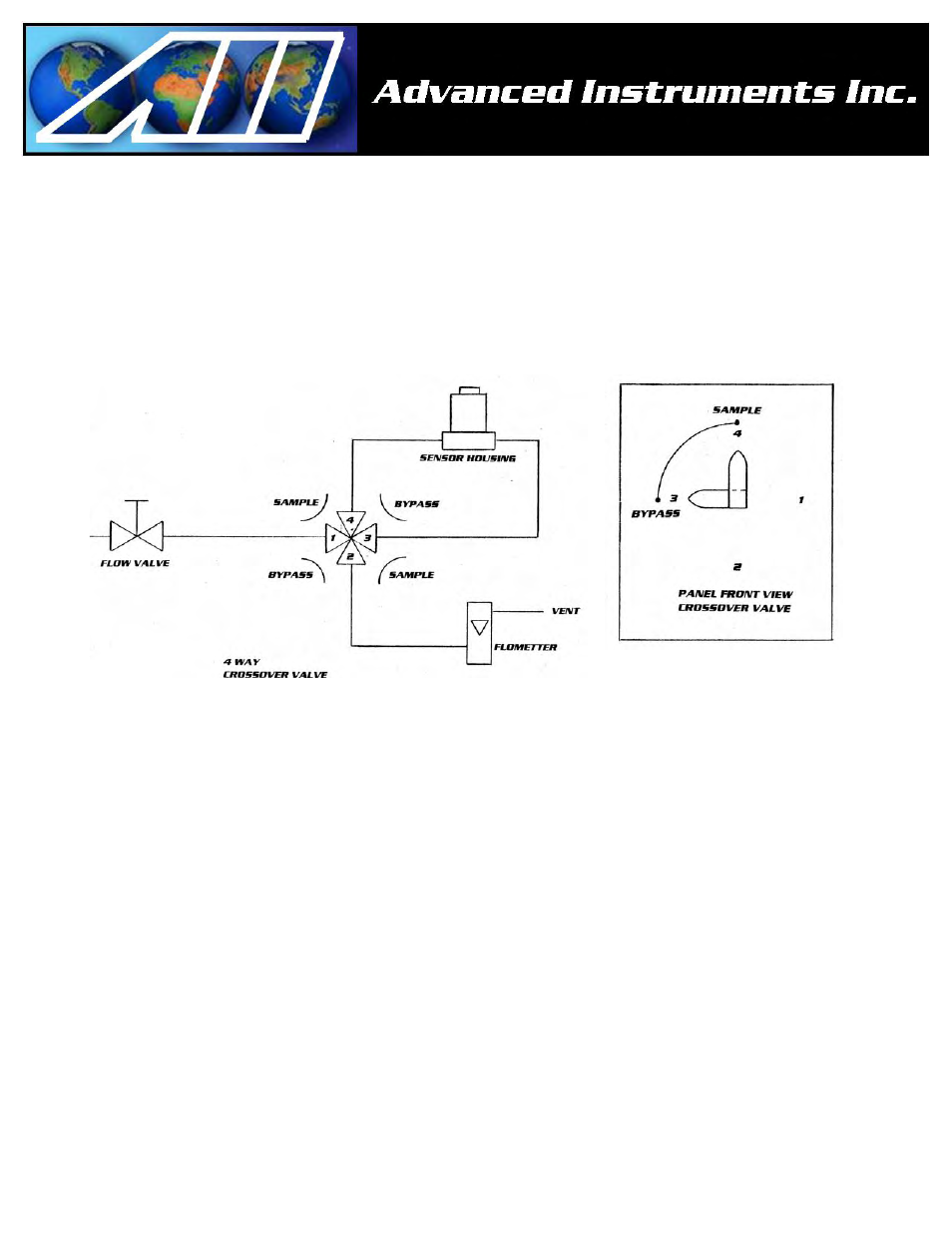
As illustrated above, the GPR-1200 MS’s internal sample system includes:
¾ 1/8” tube fittings for the inlet and outlet
¾ flow control metering valve
¾ 3-way sample/bypass valve
¾ Stainless steel sensor housing with an o-ring seal for ppb capability
¾ Flow indicator common to bypass and sample paths
Caution: Do not place your finger over the vent (it pressurizes the sensor) to test the flow indicator when gas is
flowing to the sensor. Removing your finger (the restriction) generates a vacuum on the sensor and may damage
the sensor (voiding the sensor warranty).
Procedure:
1. Review the end of the Span Calibration procedure beginning with step #28.
2. Select the desired sampling mode - auto or if manual, the range that provides maximum resolution.
3. Use metal tubing to transport the sample gas to the analyzer.
4. The main consideration is to eliminate air leaks which can affect oxygen measurements above or below the
20.9% oxygen concentration in ambient air - ensure the sample gas tubing connections fit tightly into the 1/8”
male NPT to tube adapter, and, the NPT end is taped and securely tightened into the mating male quick
disconnect fittings which mate with the female fittings on the analyzer
5. Assure there are no restrictions in the sample gas lines – inlet or vent.
6. Refer to the section on Pressure & Flow: