6 maintenance, Sensor replacement – Analytical Industries GPR-2500 A Oxygen Analyzer User Manual
Page 31
31
6 Maintenance
Generally, cleaning the electrical contacts or replacing filter elements is the extent of the maintenance
requirements of this transmitter.
Sensor Replacement
Periodically, the oxygen sensor will require replacement. The operating life is determined by a number of factors
that are influenced by the user and therefore difficult to predict. The Features & Specifications define the normal
operating conditions and expected life of the standard sensor utilized by the GPR-2500A transmitter. Expected
sensor life is inversely proportional to changes in oxygen concentration, pressure and temperature.
Serviceability: Except for replacing the oxygen sensor, there are no parts inside the transmitter for the operator
to service. Only trained personnel with the authorization of their supervisor should conduct maintenance.
Caution: DO NOT open the oxygen sensor. The sensor contains a corrosive liquid electrolyte that could be harmful
if touched or ingested, refer to the Material Safety Data Sheet contained in the Owner’s Manual. Avoid contact with
any liquid or crystal type powder in or around the sensor or sensor housing, as either could be a form of
electrolyte. Leaking sensors should be disposed of in accordance with local regulations.
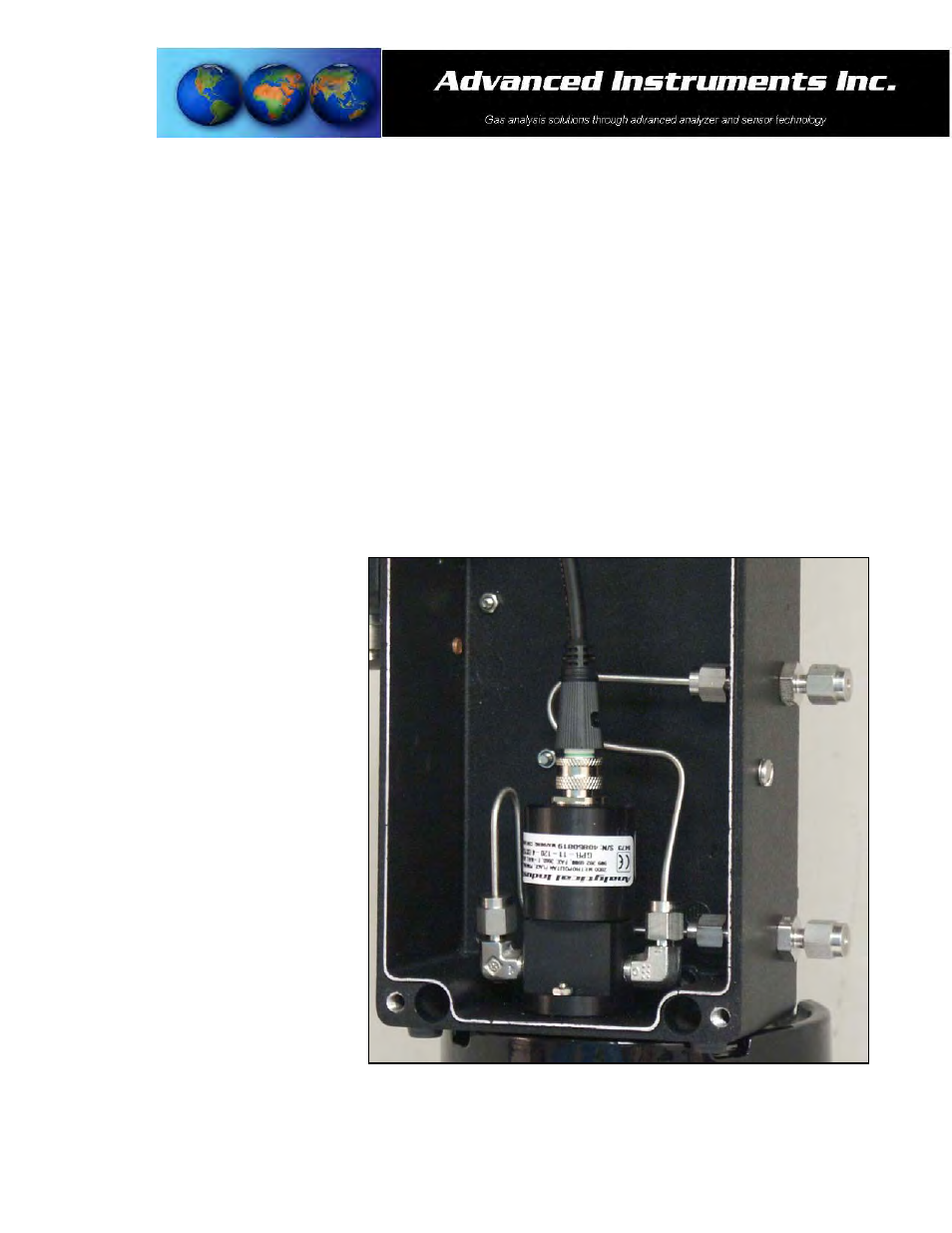
Integral Oxygen Sensor:
1. Remove the four (4) screws
securing the top section of the
enclosure, set them aside for
reinstallation and raise the hinged
top section 180º until it locks in
place.
2. Caution: Do not remove or discard
the gaskets from either the
enclosure or junction box. Failure to
reinstall either gasket will void the
NEMA 4 rating and RFI protection.
3. The transmitters design provides
protection from RFI that is
maintained by leaving specific
mating areas of the enclosure
unpainted to maintain conductivity
the gasket, top and bottom sections
of the enclosure. These unpainted
areas are protected by gaskets and
contribute to maintaining the NEMA
4 rating. Do not paint these areas.
Painting will negate the RFI
protection.
4. Unscrew the knurled lock nut
attached to the female plug/cable
from the connector attached to the sensor.
5. Grasp the female plug/cable and pull it from the male connector on the sensor on the sensor to disconnect.