Analytical Industries GPR-2500 A Oxygen Analyzer User Manual
Page 16
16
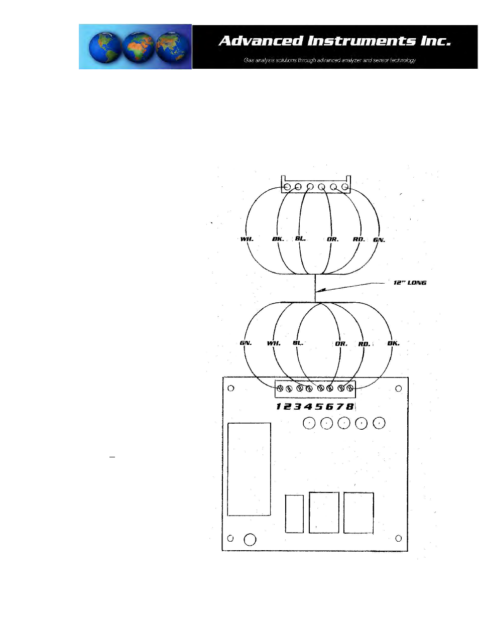
The 4-20mA signal output, power fail, alarm relay contacts, and, output connections are made to a terminal block
mounted on a PCB located in the bottom half of the front cover of the enclosure and appear upside when the
hinged enclosure is open and front cover swings up as illustrated below. The PCB also includes a transformer to
power the alarm relays. The main processing display PCB is located in the upper half of the front cover of the
enclosure.
To assure proper grounding, connect the 4-20mA signal output to the external device (PLC, DCS, etc.) before
attempting any zero or span adjustments.
Procedure:
1. Remove the four (4) screws securing the
protection Plexiglas guard.
2. Separate the shielding from the wires of
the cable.
3. Ensure the positive and negative
terminals of the incoming 24VDC power
supply are connected to the appropriate
terminals of the barrier strip as marked.
4. The output connections enter the GPR-
2500A from the hole provided in the right
side of the enclosure. Note: The user is
responsible for providing the appropriate
conduit and fittings.
5. Connect the shielding of the cable to the
ground screw. Note: The terminals snap
together, making it possible to detach the
section with the ground, install the
shielded cable and reinstall.
6. The 4-20mA current output is obtained
by connecting the current measuring
device between the positive and negative
terminals of the OUTPUT 4-20mA.
7. To check the signal output of the 4-20mA
E/I integrated circuit connect an ammeter
as the measuring device and confirm the
output is within +0.1mA of 4mA.
8. Replace the protective Plexiglas guard
and secure.
Caution: To assure proper grounding,
connect the 4-20mA signal output to the
external device (PLC, DCS, etc.) before
attempting any zero or span adjustments.