Analytical Industries GPR-2500 A Oxygen Analyzer User Manual
Page 21
21
Establishing Power to the Electronics:
Once the two wires of the shielded cable are properly connected to the
terminals inside the junction box as described above, connect the other
end of the two wires to a suitable 12-36V DC power supply with
negative ground such as a PLC, DCS, etc.
The digital display responds instantaneously. When power is applied,
the transmitter performs several diagnostic system status checks termed
“START-UP TEST” as illustrated below:
START-UP TEST
ELECTRONICS – PASS
TEMP SENSOR – PASS
BAROMETRIC SENSOR – PASS
REV. 1.61
Note: The transmitter display defaults to the sampling mode when 30
seconds elapses without user interface.
3.3
%
AUTO SAMPLING
10% RANGE
24.5 C 100 KPA
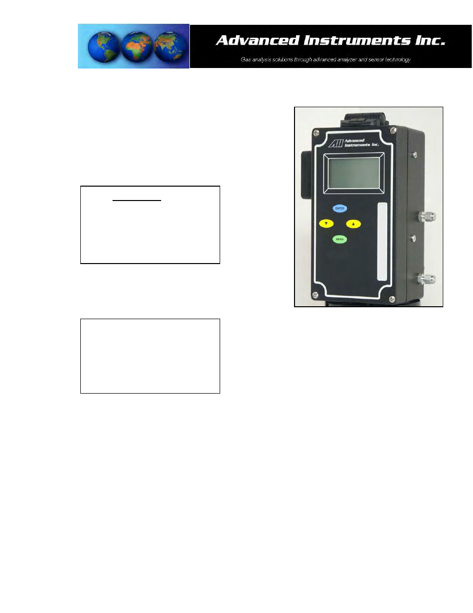
Menu Navigation:
The four (4) pushbuttons located on the front of the transmitter operate the micro-processor:
1. green ENTER (select)
2. yellow UP ARROW
3. yellow DOWN ARROW
4. blue MENU (escape)