Analytical Industries GPR-2500 A Oxygen Analyzer User Manual
Page 15
15
Electrical Connections:
Electrical connections to the GPR-2500A are made at two different
locations within the transmitters.
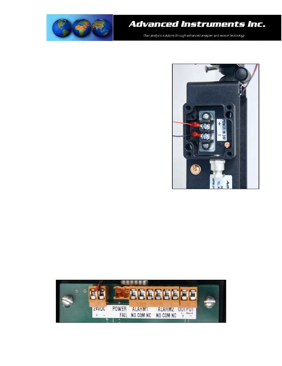
Power requirements consist of a two wire shielded cable and a 12-36V
DC with negative ground power supply. Incoming power is connected
via a terminal strip found in the junction box on the left side of the
GPR-2500A enclosure.
Caution: The integral 4-20mA converter is internally powered and
does not require external power. DO NOT supply any voltage to either
of the two terminals of the 4-20mA output or the 4-20mA converter
will be damaged.
To assure proper grounding, connect the 4-20mA signal output to the
external device (PLC, DCS, etc.) before attempting any zero or span
adjustments.
Procedure:
1. Remove the front cover of the junction box located on left side of
the transmitters by removing the four (4) screws securing the
cover and set them aside for reinstallation.
2. Loosen the nut on the cable gland.
3. Separate the shielding from the wires of the cable.
4. Thread the wires through the cable gland into the inside of the junction box.
5. Connect the two wires to the two (2) screw type terminals of the barrier strip inside the junction box.
6. Ensure the positive and negative terminals of the power supply are connected to the appropriate terminals of
the barrier strip as marked.
7. Connect the shielding of the cable to the copper ground screw inside the junction box.
8. Replace the junction box cover ensuring the gaskets are in place and tighten the four (4) screws.
9. Tighten the cable gland to maintain NEMA 4 rating.
The incoming power from the external junction box is interconnected internally to the 24VDC terminal of the PCB
with the alarm and 4-20mA output terminals as illustrations below.