Start-up – Analytical Industries GPR-2500 A Oxygen Analyzer User Manual
Page 11
11
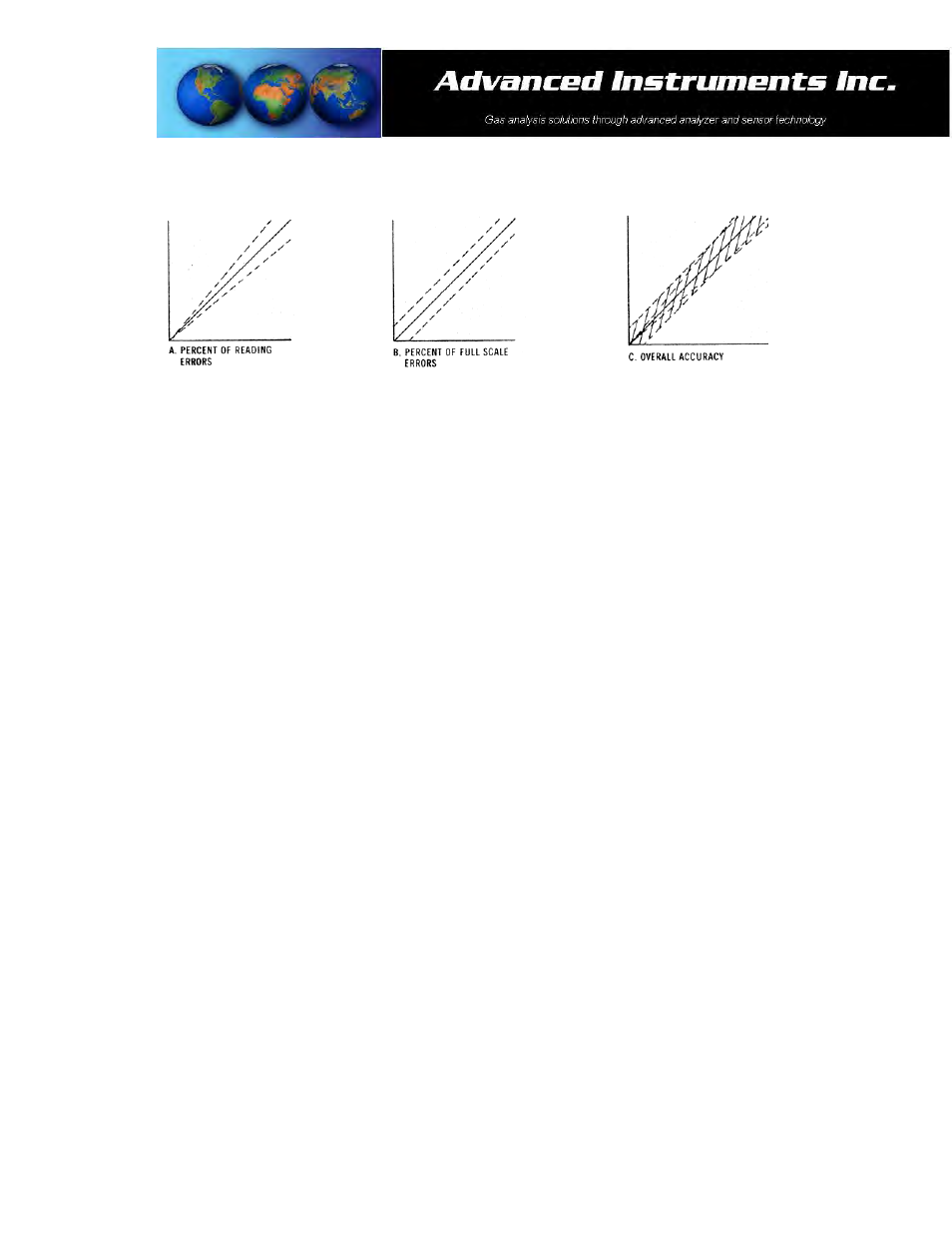
Example: As illustrated by Graph A any error, play in the multi-turn span pot or the temperature compensation
circuit, during a span adjustment at 20.9% (air) of full scale range would be multiplied by a factor of 4.78
(100/20.9) if used for measurements of 95-100% oxygen concentrations. Conversely, an error during a span
adjustment at 100% of full scale range is reduced proportionately for measurements of lower oxygen
concentrations.
Recommendation: Calibrating with a span gas approximating 80% of the full scale range one or two ranges
higher than the full scale range of interest is recommended for 'optimum calibration accuracy'. Always calibrate at
the same temperature and pressure of the sample gas stream.
Start-up
The GPR-2500A Oxygen Transmitter has been tested, calibrated at the factory prior to shipment with the sensor
installed and is fully operational from the shipping container. Allow the transmitters to stabilize for 30 minutes and
then recalibrate the device as instructed below.
Installation Considerations:
The GPR-2500A consists of a two circuit boards, sensor housing and sample 1/8” sample inlet and vent connections
housed in a NEMA 4X rated enclosure. The complete transmitter package measures 9Hx4Wx3.5”D and is suitable
for mounting on any vertical flat surface.
For optimum accuracy zero and calibrate a transmitter after it has been allowed to stabilize, typically 24-36 hours
after installation. Assuming the initial zero is performed according to the procedure described herein, the analyzer
should not require zeroing again until the either the sensor is replaced or a change is made to the sample system
or gas lines. Following the initial zero and calibration, the analyzer should not require span calibration again for up
to 3 months under “normal” application conditions as described in the published specifications.
Note: As described below, zeroing the transmitter is recommended only for measurements below 1% and not
practical for measurement ranges above 1%. The low end sensitivity (zero capability) has been verified at the
factory; however, no ZERO OFFSET adjustment has been made. A factory adjustment would be meaningless
because of the difference in sample systems and leakage factors between the factory set-up and the actual
application conditions.
¾ Assemble the necessary hardware for mounting the transmitter and optional components - such as coalescing
or particulate filters and pumps, 1/8” metal or plastic tubing for interconnecting the transmitter and optional
components.
¾ Temperature: The sample must be sufficiently cooled before it enters the transmitter and any optional
components. A coiled 10 foot length of ¼” stainless steel tubing is sufficient for cooling sample gases as high
as 1,800ºF to ambient.