P5g41-m evo parallel port connector lpt, Ieee 1394a connector, P5g41-m evo – Asus P5G41-M EVO User Manual
Page 27: P5g41-m evo floppy disk drive connector, Floppy
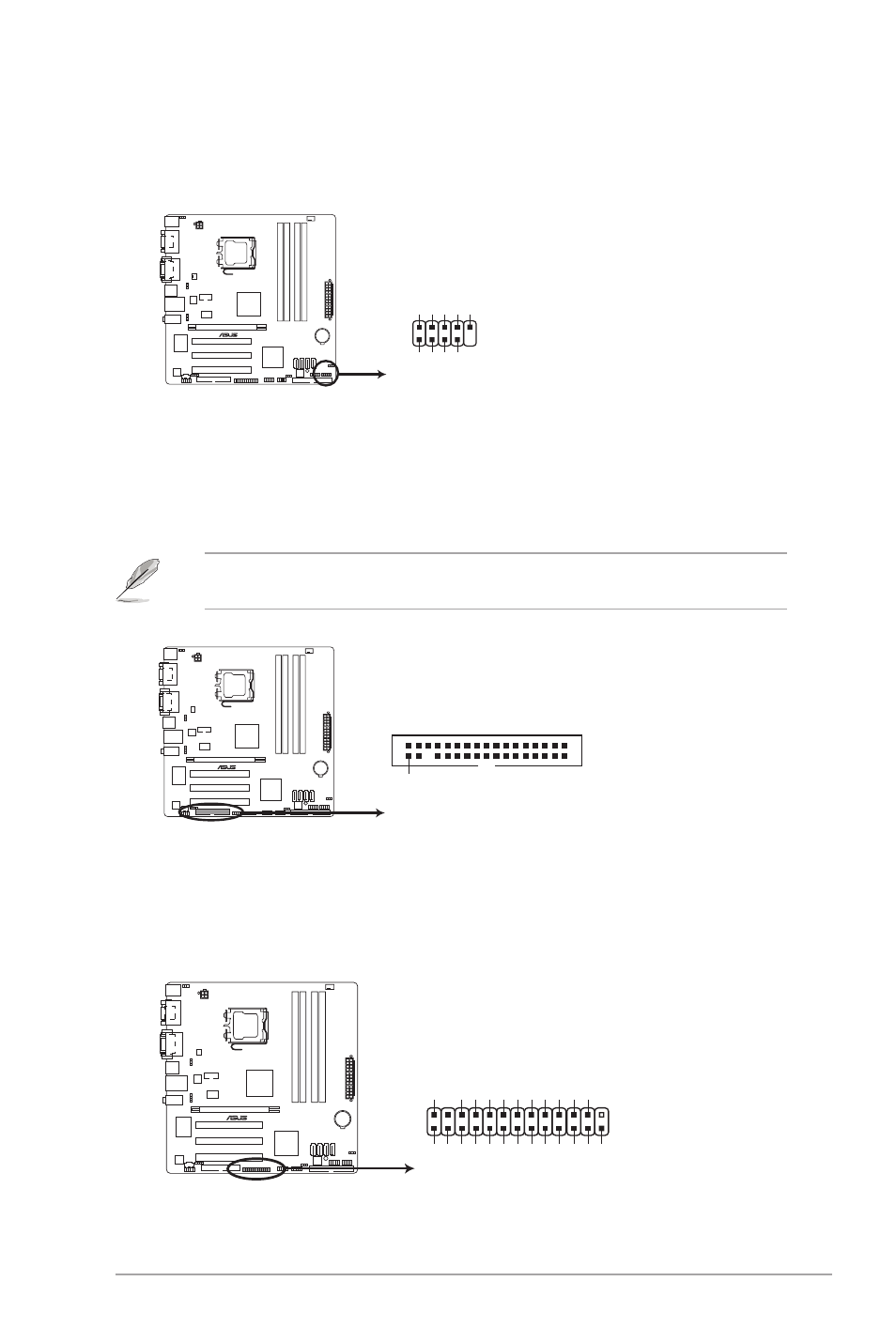
12. IEEE 1394a connector (10-1 pin IE1394_1)
This port is for an IEEE1394a port. Connect the IEEE1394a module cable to this
connecter, then install the module to a slot opening at the back of the system chassis.
P5G41-M EVO
P5G41-M EVO
IEEE 1394a Connector
PIN 1
TPA1-
GND
TPB1-
+
12
V
GND
TPA1+
GND
TPB1+
+12V
IE1394_1
13. Floppy disk drive connector (34-1 pin FLOPPY)
This connector is for the provided floppy disk drive (FDD) signal cable. Insert one end
of the cable to this connector, then connect the other end to the signal connector at the
back of the floppy disk drive.
P5G41-M EVO
FLOPPY
NOTE:Orient the red markings
on the floppy ribbon cable to PIN 1.
PIN1
P5G41-M EVO Floppy disk drive connector
Pin 5 on the connector is removed to prevent incorrect cable connection when using a FDD
cable with a covered Pin 5.
14. LPT connector (26-1 pin LPT)
The LPT (Line Printing Terminal) connector supports devices such as a printer. LPT
standardizes as IEEE 1284, which is the parallel port interface on IBM PC-compatible
computers.
P5G41-M EVO
P5G41-M EVO Parallel Port Connector
LPT
PIN
1
STB# PD
0
PD
1
PD
2
PD
3
PD
4
PD
5
PD
6
PD
7
ACK# BUSY
PE
SLCT
AF
D
ERR# INIT
#
SLIN
#
GND GND GND GND GND GND GND GND
ASUS P5G41-M EVO
1-17