P5g41-m evo digital audio connector – Asus P5G41-M EVO User Manual
Page 25
8.
System panel connector (10-1 pin F_PANEL)
This connector supports several chassis-mounted functions.
•
System power LED (2-pin PLED)
This 2-pin connector is for the system power LED. Connect the chassis power LED
cable to this connector. The system power LED lights up when you turn on the system
power, and blinks when the system is in sleep mode.
•
Hard disk drive activity LED (2-pin +HDLED)
This 2-pin connector is for the HDD Activity LED. Connect the HDD Activity LED cable
to this connector. The IDE LED lights up or flashes when data is read from or written to
the HDD.
•
Power/Soft-off button (2-pin PWRBTN)
This 2-pin connector is for the system power button. Pressing the power button turns
the system ON or puts the system in SLEEP or SOFT-OFF mode depending on the
BIOS settings. Pressing the power switch for more than four seconds while the system
is ON turns the system OFF.
•
Reset button (2-pin RESET)
This 2-pin connector is for the chassis-mounted reset button for system reboot without
turning off the system power.
P5G41-M EVO
PIN 1
PWR BTN
PLED
+
PLED
-
PWR
GND
IDE_LED
+
IDE_LED
-
Groun
d
Rese
t
F_PANEL
PWR LED
HD_LED
RESET
P5G41-M EVO System panel connector
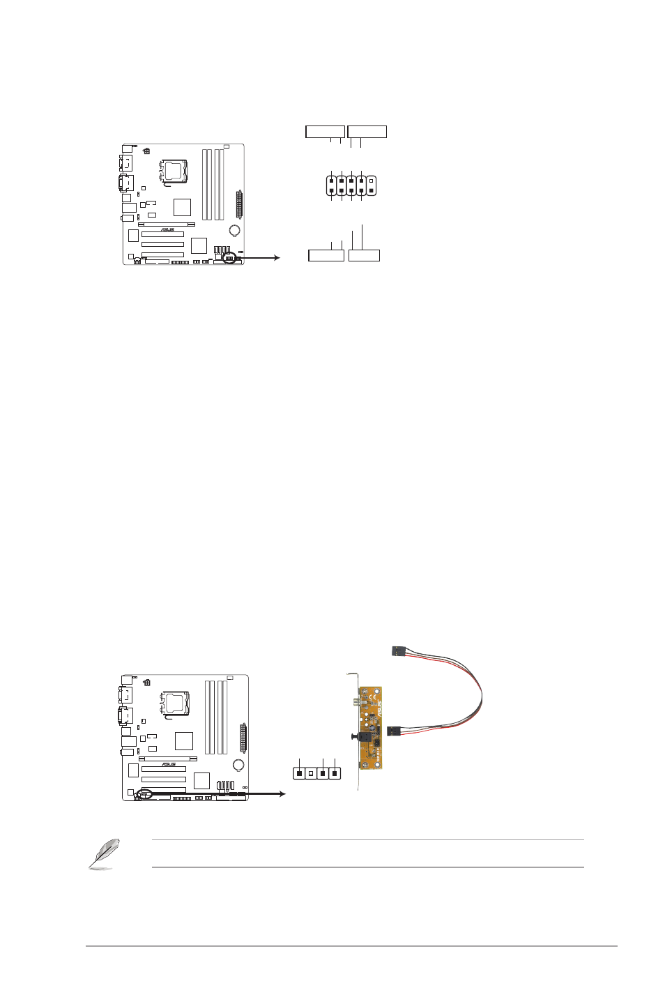
9.
Digital audio connector (4-1 pin SPDIF_OUT)
This connector is for an additional Sony/Philips Digital Interface (S/PDIF) port.
SPDIF_OUT
+5
V
SPDIFOU
T
GND
P5G41-M EVO
P5G41-M EVO Digital audio connector
The S/PDIF module is purchased separately.
ASUS P5G41-M EVO
1-15