2 screw holes, 3 motherboard layout, Chapter 1: product introduction – Asus Q87T User Manual
Page 10: Place this side towards the rear of the chassis
1-2
Chapter 1: Product introduction
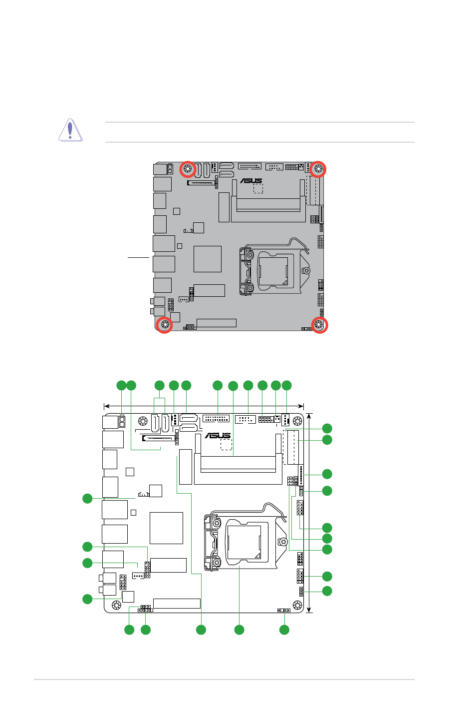
1.2.2
Screw holes
Place six screws into the holes indicated by circles to secure the motherboard to the chassis.
Do not overtighten the screws! Doing so can damage the motherboard.
Q87T
Place this side
towards the rear
of the chassis
1.2.3
Motherboard layout
Q87T
F_PANEL
COM1
SATA_PWRCON
AAFP
CUSTOM
HP-OUT
LAN1
LAN2
USB3_56
USB3_34
HDMI
DP
DC_PWR
MIC
CLRTC
CHA_FAN
CPU_FAN
ALC887
-VD2
128Mb
BIOS
17cm(6.7in)
17cm(6.7in)
LPC_DEBUG
MON_SW_PANEL
LCD_BLKT_PANEL
EDP
LVDS
USB3_12
SATA6G_3
SATA6G_1
SATA6G_4 SATA6G_2
DMIC
USB14
DIS_ME
FPD_SEL
VCC_PWR_SEL
CHASSIS
BLKT_PWR_SEL
INT_SPK
MSATA_MPCIE
PCIEX4
WLAN
ATX19V1
DDR3 DIMM_B1 (64bit, 204-pin module)
DDR3 DIMM_A1 (64bit, 204-pin module)
USB78
USB910
BATT_CON
RTL
8111G
LGA1150
Intel
®
Q87
Super
I/O
ASM
1442K
9
3
2
5
6
7
1
14
11
16
15
14
10
13
12
17
20
21
4
8
19
23
14
18
22
24
25
4 3
- P5B Premium Vista Edition (188 pages)
- P5B (140 pages)
- P5B (56 pages)
- P5KPL-VM/1394/SI (94 pages)
- M2N68-CM (28 pages)
- P5GD1-VM (92 pages)
- P5AD2-E Premium (2 pages)
- P5GD1-VM (88 pages)
- P5AD2 Premium (8 pages)
- DELUXE A7N8X-E (114 pages)
- P5KPL-AM SE (40 pages)
- P5KPL-AM SE (38 pages)
- P5KPL-AM SE (62 pages)
- P4S8X-X (64 pages)
- P5K-VM (98 pages)
- K8V-X SE (82 pages)
- M2N68-AM SE2 (40 pages)
- P4P800 SE (125 pages)
- P4P800 SE (16 pages)
- DELUXE SERIES M3A32-MVP (176 pages)
- P5AD2 Deluxe (148 pages)
- M4A79 Deluxe (122 pages)
- A7V266-E (108 pages)
- Application Manual (5 pages)
- Application Manual (11 pages)
- Application Manual (10 pages)
- Application Manual (4 pages)
- Application Manual (8 pages)
- Application Manual (2 pages)
- Application Manual (6 pages)
- Application Manual (9 pages)
- Application Manual (3 pages)
- Application Manual (1 page)
- M4A88T-I DELUXE (70 pages)
- M4A88T-I DELUXE (44 pages)
- P9X79 DELUXE (2 pages)
- RAMPAGE IV GENE (1 page)
- P9X79 (156 pages)
- P8H61-M PLUS V3 (64 pages)
- A85XM-A (78 pages)
- M4A78L-M LE (64 pages)
- M2N68-AM (96 pages)
- M2N68-AM (62 pages)
- M2N68-AM (38 pages)
- Blitz Formula (3 pages)