Asus V2-PH1 User Manual
Page 62
4-10
Chapter 4: Motherboard info
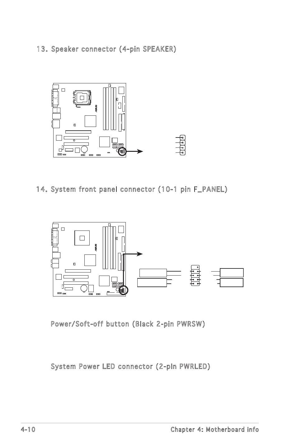
14. System front panel connector (10-1 pin F_PANEL)
This connector supports several front panel chassis-mounted
functions.
®
F_PANEL
System panel connector
*
Requires an ATX power supply.
PWR
Ground
GND
Reset
IDE_LED+
IDE_LED-
RESET
IDE LED
PWRSW
PWR_LED-
PWRLED
PWR_LED+
13. Speaker connector (4-pin SPEAKER)
This 4-pin connector is for the chassis-mounted system warning
speaker. The speaker allows you to hear system beeps and warnings.
®
Speaker out connector
SPEAKER
+5V
1
GND
Speak Out
GND
• Power/Soft-off button (Black 2-pin PWRSW)
This connector is for the system power button. Pressing the power
button turns the system ON or puts the system in SLEEP or SOFT-OFF
mode depending on the BIOS settings. Pressing the power switch for
more than four seconds while the system is ON turns the system OFF.
• System Power LED connector (2-pin PWRLED)
This 2-pin connector is for the system power LED. The system power
LED lights up when you turn on the system power, and blinks when
the system is in sleep mode.