4 internal components, 7 asus vintage2-ph1 – Asus V2-PH1 User Manual
Page 17
1-7
ASUS Vintage2-PH1
1.4
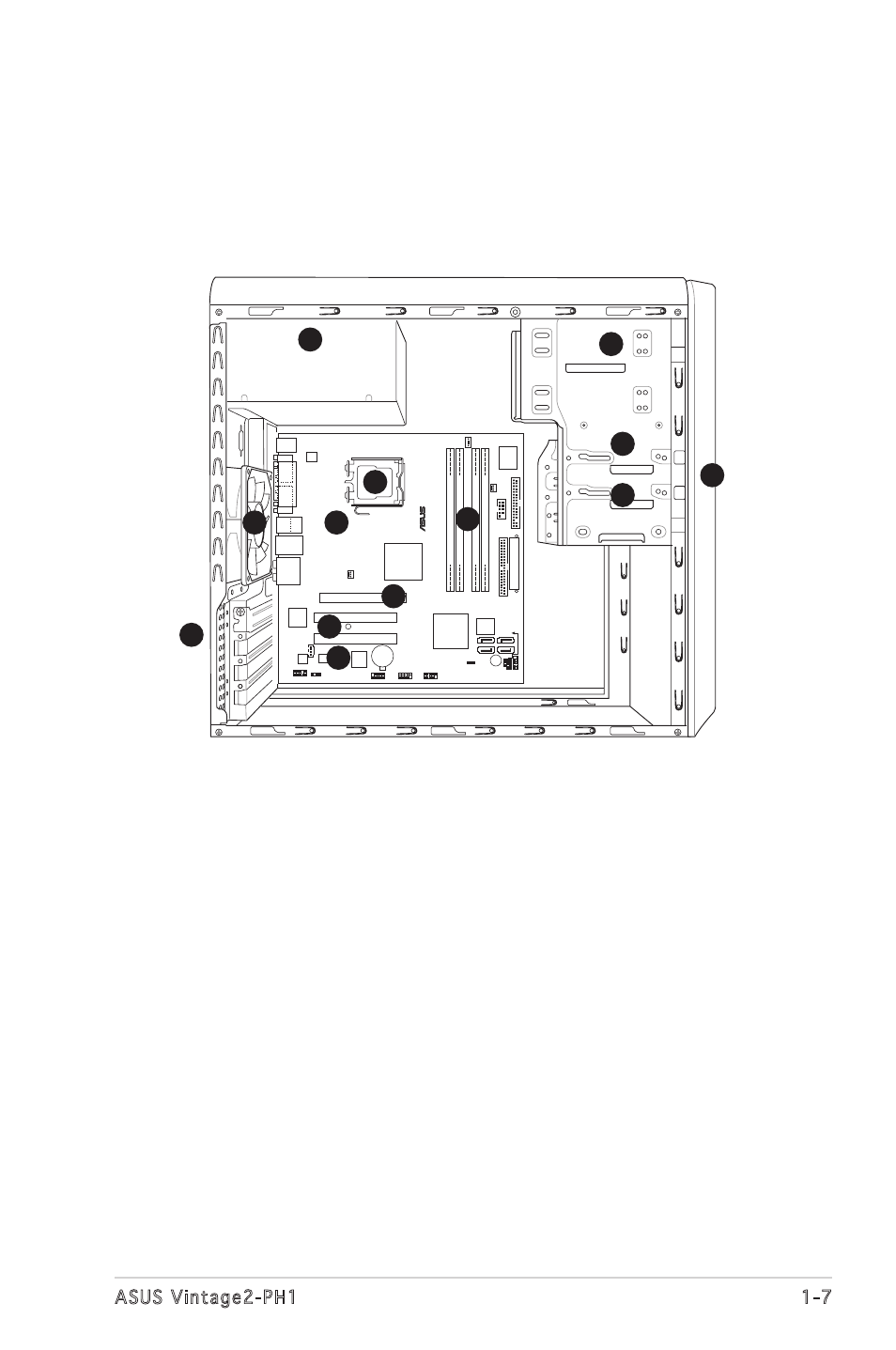
Internal components
The illustration below is the internal view of the system when you remove
the top cover and the power supply unit. The installed components are
labeled for your reference. Proceed to Chapter 2 for instructions on
installing additional system components.
CR2032 3V
Lithium Cell
CMOS Power
CD
Su
pe
r
I/O
Intel FWH
4Mb
ATX12V
FLOPPY
AAFP
DDR DIMM_A1 (64 bit,240-pin
module
)
SB_PWR
F_P
ANEL
CHASSI
S
USB78
USB56
CLRTC
PCI1
Intel
®
GMCH
945G
Intel
®
ICH7
DDR DIMM_A2 (64 bit,240-pin
module
)
DDR DIMM_B1 (64 bit,240-pin
module
)
DDR DIMM_B2 (64 bit,240-pin
module
)
CHA_FAN
CPU_FAN
PRI_IDE
EA
TXPW
R
PCI2
SPDIF_OUT
Intel
82573L
PS/2KBMS
T: Mouse
B: Keyboard
PCIEX1_1
PCIEX16
COM1
PARALLEL
POR
T
VGA
PLED
®
SATA1
SATA2
SATA4
SATA3
BUZZ
PWR_F
AN
SPEAKER
COM2
ALC882
TI
TSB43AB22A
IE1394_2
LGA775
LAN_USB34
AUDIO
USB1
USB2
Bottom:
1394
Top:
1. Front panel cover
2. 5.25-inch optical drive bays
3. Hard disk drive bay
4. Floppy disk drive bay
5. Power supply unit
6. CPU socket
7. DIMM sockets
8. ASUS motherboard
9. Chassis fan
10. PCI Express x16 slot
11. PCI slots
12. PCI Express x1 slot
13. Metal bracket lock
6
1
2
3
4
13
11
9
7
8
5
12
10