2 motherboard overview, 1 motherboard layout, 2 layout contents – Asus P7Q57-M DO User Manual
Page 12: Motherboard overview -2 1.2.1, Motherboard layout -2, Layout contents -2, Place this side towards the rear of the chassis, Chapter 1: product introduction 1-2
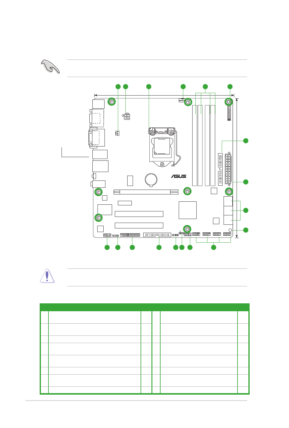
1.2
Motherboard overview
1.2.1
Motherboard layout
Place eight screws into the holes indicated by circles to secure the motherboard to the
chassis. DO NOT overtighten the screws! Doing so can damage the motherboard.
Ensure that you install the motherboard into the chassis in the correct orientation. The edge
with external ports goes to the rear part of the chassis.
1.2.2
Layout contents
Connectors/Jumpers/Slots/LED
Page Connectors/Jumpers/Slots/LED
Page
1. CPU and Chassis fan connectors (4-pin CPU_FAN,
3-pin CHA_FAN)
1-13 9. USB connectors (10-1 pin USB78, USB910,
USB1112, USB1314)
1-11
2. ATX power connectors (24-pin EATXPWR, 4-pin
ATX12V)
1-14 10. System panel connector (10-1 pin F_PANEL) 1-15
3. Intel
®
CPU socket
11. Clear RTC RAM (3-pin CLRTC)
1-9
4. DDR3 DIMM sockets
1-3 12. Chassis intrusion connector (4-1 pin
CHASSIS)
1-13
5. TPM connector (20-1 pin TPM)
1-17 13. Floppy disk drive connector (34-1 pin
FLOPPY)
1-16
6. IDE connector (40-1 pin PRI_IDE)
1-18 14. LPT connector (26-1 pin LPT)
1-17
7. Serial ATA connectors (7-pin SATA1-6)
1-12 15. Digital audio connector (4-1 pin
SPDIF_OUT)
1-12
8. Onboard LED
1-1 16. Front panel audio connector (10-1 pin AAFP) 1-16
Place this side towards
the rear of the chassis.
P7Q57-M DO
PCI2
PCI1
PCIEX1_1
LPT
USB1314 USB1112 USB910 USB78
F_PANEL
AAFP
ATX12V
EATXPW
R
CPU_FAN
CHA_FAN
Lithium Cell
CMOS Power
Super
I/O
AUDIO
SERVICE_MODE
IC
S
9LRS954
Realtek
ALC887
Intel
WG82578DM
C0
KBMS
JMB
368
64Mb
BIOS
SB_PWR
CLRTC
CHASSIS
SPDIF_OUT
FLOPPY
24.4cm(9.6in)
24.4cm(9.6in)
LGA1156
Intel
®
Q57
DDR3 DIMM_A2 (64bit, 240-pin module)
DDR3 DIMM_A1 (64bit, 240-pin module)
DDR3 DIMM_B2 (64bit, 240-pin module)
DDR3 DIMM_B1 (64bit, 240-pin module)
DV
I
VG
A
LAN1_USB12
USB3_6
S
A
T
A
1
S
A
T
A
2
SATA3
SATA5
SATA4
SATA6
HDM
I
COM1
TPM
PRI_IDE
PCIEX16
3
2
1
4
1
5
6
2
7
8
9
10
11
12
13
14
15
16
Chapter 1: Product introduction
1-2