Asus A7S266-VM/U2 User Manual
Page 27
ASUS A7S266-VM/U2 Motherboard
1-17
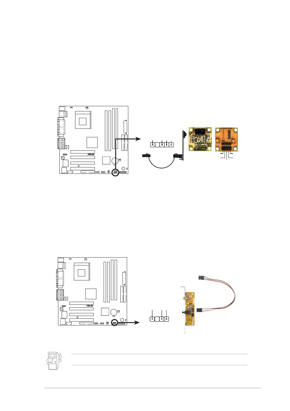
10.
S/PDIF connector (4-1 pin SPDIF_OUT1) (on audio models only)
This 4-pin connector accomodates a 4-pin S/PDIF out connector for S/PDIF
using a S/PDIF port bracket. Connect the bracket cable to this connector
then install the bracket into a slot opening at the back of the system chassis.
9.
infrared connector (5-1 pin IR_CON1)
These connectors support an optional wireless transmitting and receiving
infrared module. The module monts to a small opening on the system chassis
that supports this feature. You must also configure the UART2 Use As
parameter in BIOS to set UART2 for use with IR. Use the ten pins as shown
in Back View and connect a ribbon cable from the module to the motherboard
IR_CON1 connector according to the pin definitions.
The S/PDIF module is not included in the package.
A7S266-VM/U2
®
Front View
Back View
+5V
IRTX
IRRX
(NC)
GND
+5V
IRRX
IR
TX
GND
IR_CON1
1
A7S266-VM/U2 Infrared Module Connector
A7S266-VM/U2
®
A7S266-VM/U2 Digital Audio Connector
+5V
SPDIFOUT
GND
SPDIF_OUT1
- P5B Premium Vista Edition (188 pages)
- P5B (140 pages)
- P5B (56 pages)
- P5KPL-VM/1394/SI (94 pages)
- M2N68-CM (28 pages)
- P5AD2-E Premium (2 pages)
- P5GD1-VM (88 pages)
- P5AD2 Premium (8 pages)
- P5GD1-VM (92 pages)
- DELUXE A7N8X-E (114 pages)
- P5KPL-AM SE (62 pages)
- P5KPL-AM SE (40 pages)
- P5KPL-AM SE (38 pages)
- P4S8X-X (64 pages)
- P5K-VM (98 pages)
- K8V-X SE (82 pages)
- M2N68-AM SE2 (40 pages)
- P4P800 SE (125 pages)
- P4P800 SE (16 pages)
- DELUXE SERIES M3A32-MVP (176 pages)
- P5AD2 Deluxe (148 pages)
- M4A79 Deluxe (122 pages)
- A7V266-E (108 pages)
- Application Manual (8 pages)
- Application Manual (2 pages)
- Application Manual (6 pages)
- Application Manual (9 pages)
- Application Manual (3 pages)
- Application Manual (1 page)
- Application Manual (5 pages)
- Application Manual (11 pages)
- Application Manual (10 pages)
- Application Manual (4 pages)
- M4A88T-I DELUXE (70 pages)
- M4A88T-I DELUXE (44 pages)
- P9X79 DELUXE (2 pages)
- RAMPAGE IV GENE (1 page)
- P9X79 (156 pages)
- P8H61-M PLUS V3 (64 pages)
- A85XM-A (78 pages)
- M4A78L-M LE (64 pages)
- M2N68-AM (96 pages)
- M2N68-AM (62 pages)
- M2N68-AM (38 pages)
- Blitz Formula (1 page)